Mesh
介绍
Baffalo_Mesh 是划分3D网格的模块,主要功能是:
- 将2D的网格转换为3D的网格。
- 建立基本的3D网格体
- 雕刻3D网格
主要参考的工具箱或代码:Gibbon$^{[1][2]}$,MRST$^{[3]}$,TetGen$^{[4]}$,voronoi3d$^{[5]}$
案例
Create cube mesh (Flag=1)
%% Specifying dimensions and number of elements
m=Mesh('Mesh');
%% Create a box with hexahedral elements
cubeDimensions=[10 10 10]; %Dimensions
cubeElementNumbers=[5 5 5]; %Number of elements
m=MeshCube(m,cubeDimensions,cubeElementNumbers);
%% Plot elements
PlotFace(m,'face_alpha',1);
sec.pos=[0,0,0];
sec.vec=[1,0,0];
PlotElement(m,'section',sec);
sec.vec=[1,1,-1];
PlotElement(m,'section',sec);
建立cube体网格:

 |  |
Create cylinder mesh (Flag=2)
%Specifying dimensions and number of elements
mm=Mesh('Cylinder Mesh');
mm=MeshCylinder(mm,1,30,50,'ElementType','quad');
PlotFace(mm);
% The cyclinder is meshed using tetrahedral elements using tetgen
mm=Mesh3D(mm); % Mesh model using tetrahedral elements using tetGen
PlotElement(mm);
sec.pos=[0,0,0];
sec.vec=[1,0,0];
PlotElement(mm,'section',sec);
建立圆柱体网格:

 |  |
Create sphere mesh (Flag=3)
%Sphere parameters
numRefineStepsSphere=3;
sphereRadius=2;
mm=Mesh('Demo Sphere Mesh');
mm=MeshSphere(mm,numRefineStepsSphere,sphereRadius);
PlotFace(mm);
sec.pos=[0,0,0];
sec.vec=[1,0,0];
PlotElement(mm,'section',sec);
建立球体网格:
 |  |
Hex20 Plot (Flag=4)
%% Specifying dimensions and number of elements
m=Mesh('Mesh');
%% Create a box with hexahedral elements
beamDimensions=[10 40 10]; %Dimensions
beamElementNumbers=[4 20 4]; %Number of elements
m=MeshCube(m,beamDimensions,beamElementNumbers,'ElementType','hex20');
PlotFace(m,'marker',1);
PlotFace2(m);
二阶六面体网格绘制:
 |  |
MeshHemiSphere (Flag=5)
% Control settings
sphereRadius=1;
numElementsMantel=6;
m=Mesh('Mesh');
m=MeshHemiSphere(m,sphereRadius, numElementsMantel);
PlotFace(m);
sec.pos=[0,0,0];
sec.vec=[1,0,0];
PlotElement(m,'section',sec);
半球体网格绘制:
 |  |
Mesh plate1 (Flag=6)
% IR=211/2;
% OR=801/2;
% radius1=300/2;
% radius2=600/2;
% num=6;
% par1=100;
% Thickness=15;
IR=80/2;
OR=650/2;
radius1=420/2;
radius2=520/2;
num=6;
par1=100;
Thickness=20;
ang1=360/num-asin(par1/2/radius1)/pi*180*2;
ang2=360/num-asin(par1/2/radius2)/pi*180*2;
a=Point2D('Point Ass1');
b=Line2D('Line Ass1');
a=AddPoint(a,0,0);
a=AddPoint(a,par1,0);
a=AddPoint(a,[radius1*cos(ang1/2/180*pi);radius2*cos(ang2/2/180*pi)],...
[radius1*sin(ang1/2/180*pi);radius2*sin(ang2/2/180*pi)]);
a=AddPoint(a,[radius2*cos(-ang2/2/180*pi);radius1*cos(-ang1/2/180*pi)],...
[radius2*sin(-ang2/2/180*pi);radius1*sin(-ang1/2/180*pi)]);
b=AddCircle(b,OR,a,1);
S=Surface2D(b);
h1=Line2D('Hole Group1');
h1=AddCircle(h1,IR,a,1);
S=AddHole(S,h1);
h2=Line2D('Hole Group2','Dtol',0.1);
h2=AddCircle(h2,radius1,a,1,'sang',-ang1/2,'ang',ang1);
h2=AddLine(h2,a,3);
h2=AddCircle(h2,radius2,a,1,'sang',ang2/2,'ang',-ang2);
h2=AddLine(h2,a,4);
h2=CreateRadius(h2,1,10);
h2=CreateRadius(h2,3,10);
h2=CreateRadius(h2,5,10);
h2=CreateRadius(h2,7,10);
for i=1:num
S=AddHole(S,h2,'rot',360/num*(i-1));
end
m=Mesh2D('Mesh1');
m=AddSurface(m,S);
m=SetSize(m,20);
m=Mesh(m);
Plot(m);
mm=Mesh('Mesh');
mm=Extrude2Solid(mm,m,Thickness,3);
PlotFace(mm);
绘制平板1
 |  |
Mesh plate2 (Flag=7)
% Parameter
IR=640/2;
OR=768/2;
par=442;
radius=70;
R=116/2;
num=6;
Rp=460;
t=30;
hd=17.5;
sang=asin(R/OR)/pi*180;
ang=360/num-2*sang;
a=Point2D('Point Ass1');
b=Line2D('Line Ass1','Dtol',1);
a=AddPoint(a,0,0);
for i=1:num
b=AddCircle(b,OR,a,1,'sang',sang+ang-360/num*(i-1),'ang',-ang);
theta=-360/num/180*pi*(i-1);
mat=[cos(theta),-sin(theta);sin(theta),cos(theta)];
p1=mat*[sqrt(OR^2-R^2),par;R,R];
p1=p1';
a=AddPoint(a,p1(:,1),p1(:,2));
b=AddLine(b,a,2+3*(i-1));
p2=mat*[par;0];
p2=p2';
a=AddPoint(a,p2(1,1),p2(1,2));
b=AddCircle(b,R,a,3+3*(i-1),'sang',90+theta/pi*180,'ang',-180);
p3=mat*[par,sqrt(OR^2-R^2);-R,-R];
p3=p3';
a=AddPoint(a,p3(:,1),p3(:,2));
b=AddLine(b,a,4+3*(i-1));
end
for i=1:num
b=CreateRadius(b,1+6*(i-1),radius);
b=CreateRadius(b,5+6*(i-1),radius);
end
Plot(b,'clabel',1,'equal',1)
S=Surface2D(b);
h1=Line2D('Hole Group1');
h1=AddCircle(h1,IR,a,1);
S=AddHole(S,h1);
a1=Point2D('Point Ass2');
a1=AddPoint(a1,Rp,0);
h2=Line2D('Hole Group2');
h2=AddCircle(h2,hd/2,a1,1);
for i=1:num
S=AddHole(S,h2,'rot',360/num*(i-1));
end
m=Mesh2D('Mesh1');
m=AddSurface(m,S);
m=SetSize(m,20);
m=Mesh(m);
Plot(m);
mm=Mesh('Mesh');
mm=Extrude2Solid(mm,m,t,3);
PlotFace(mm);
绘制平板2:
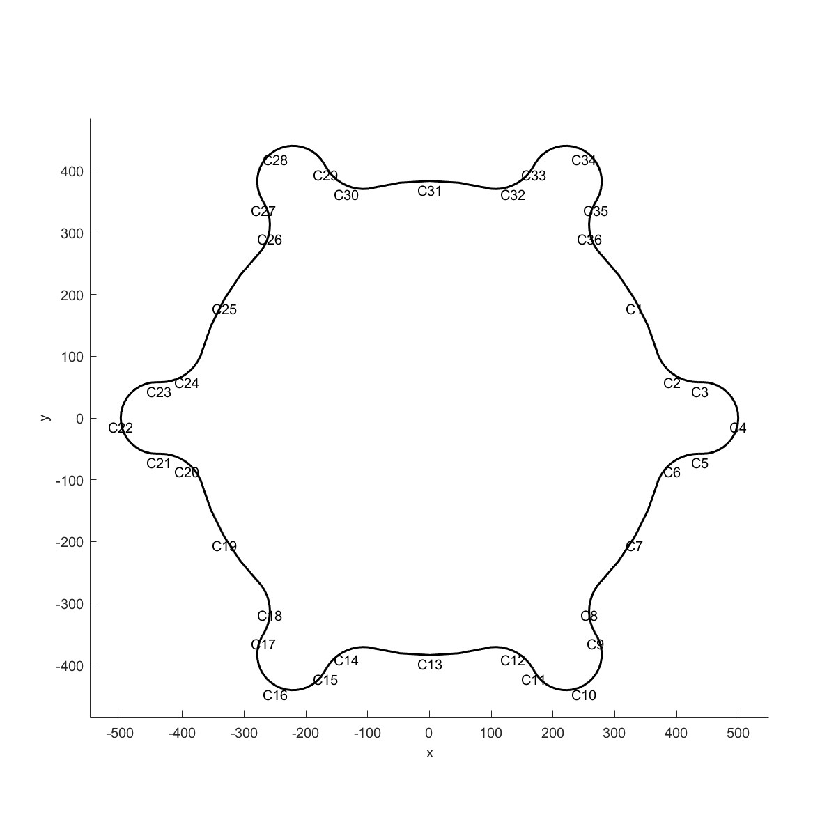
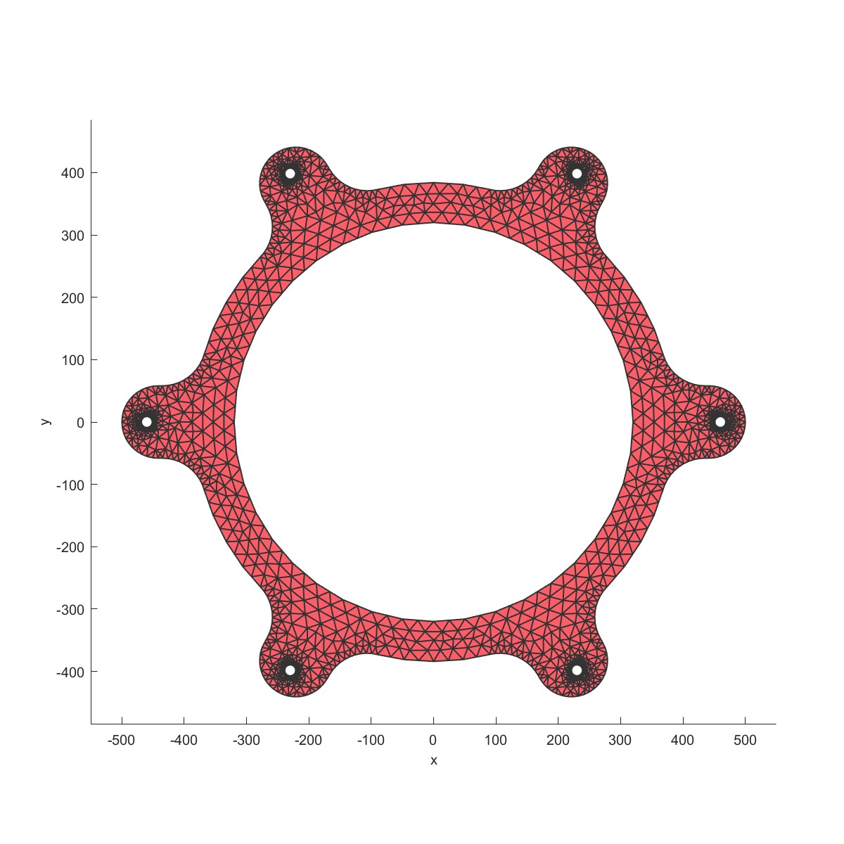 | 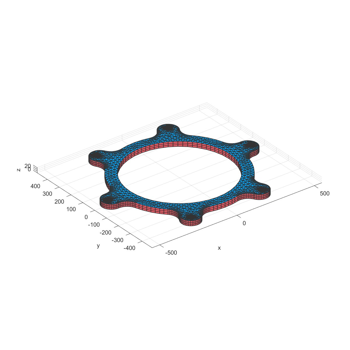 |
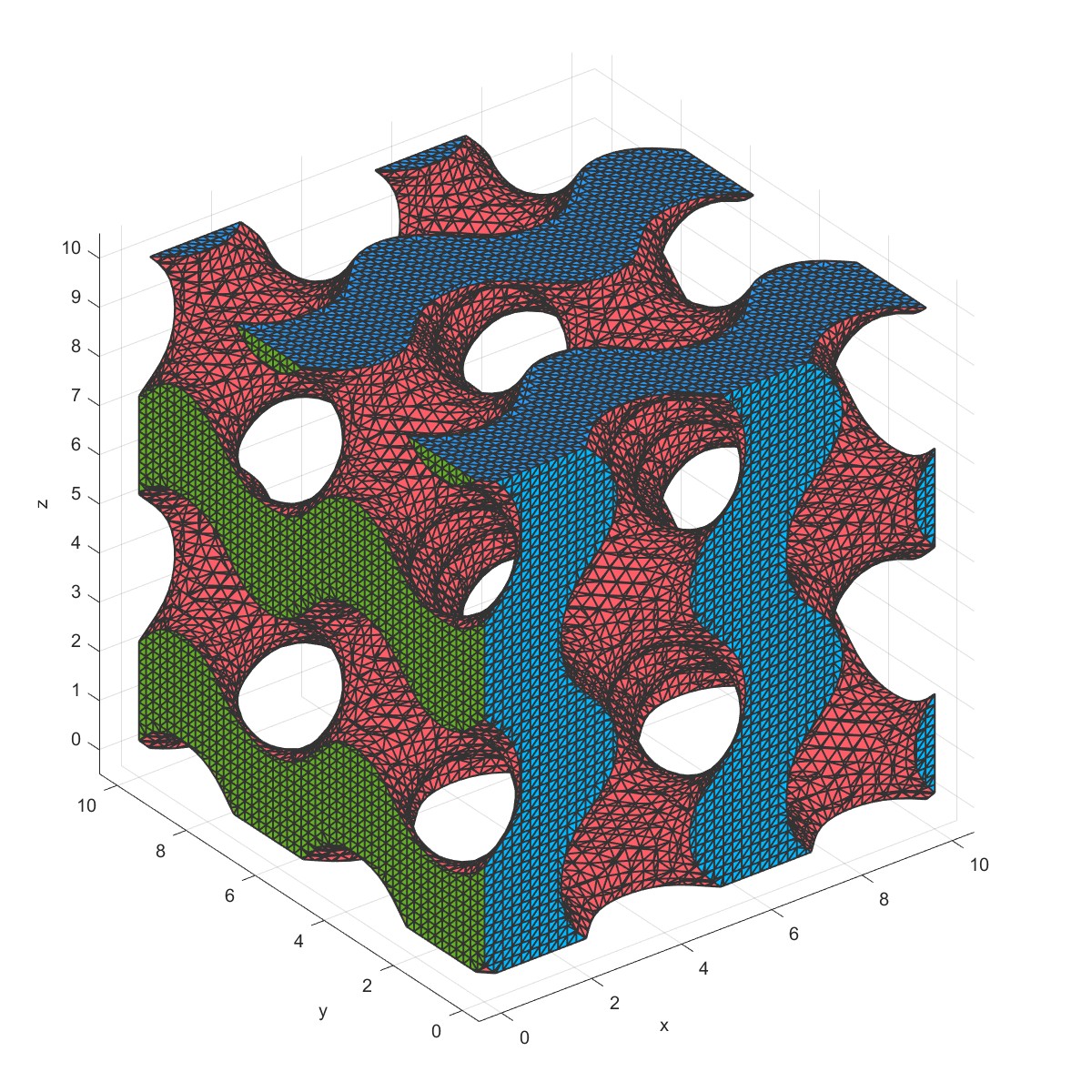
Mesh TriplyPeriodicMinimalSurface (Flag=8)
%Gyroid
Length=10; % Length of the sample
mm=Mesh('Demo Gyroid Mesh');
mm=MeshTriplyPeriodicMinimalSurface(mm,Length);
PlotFace(mm);
建立围观元胞:
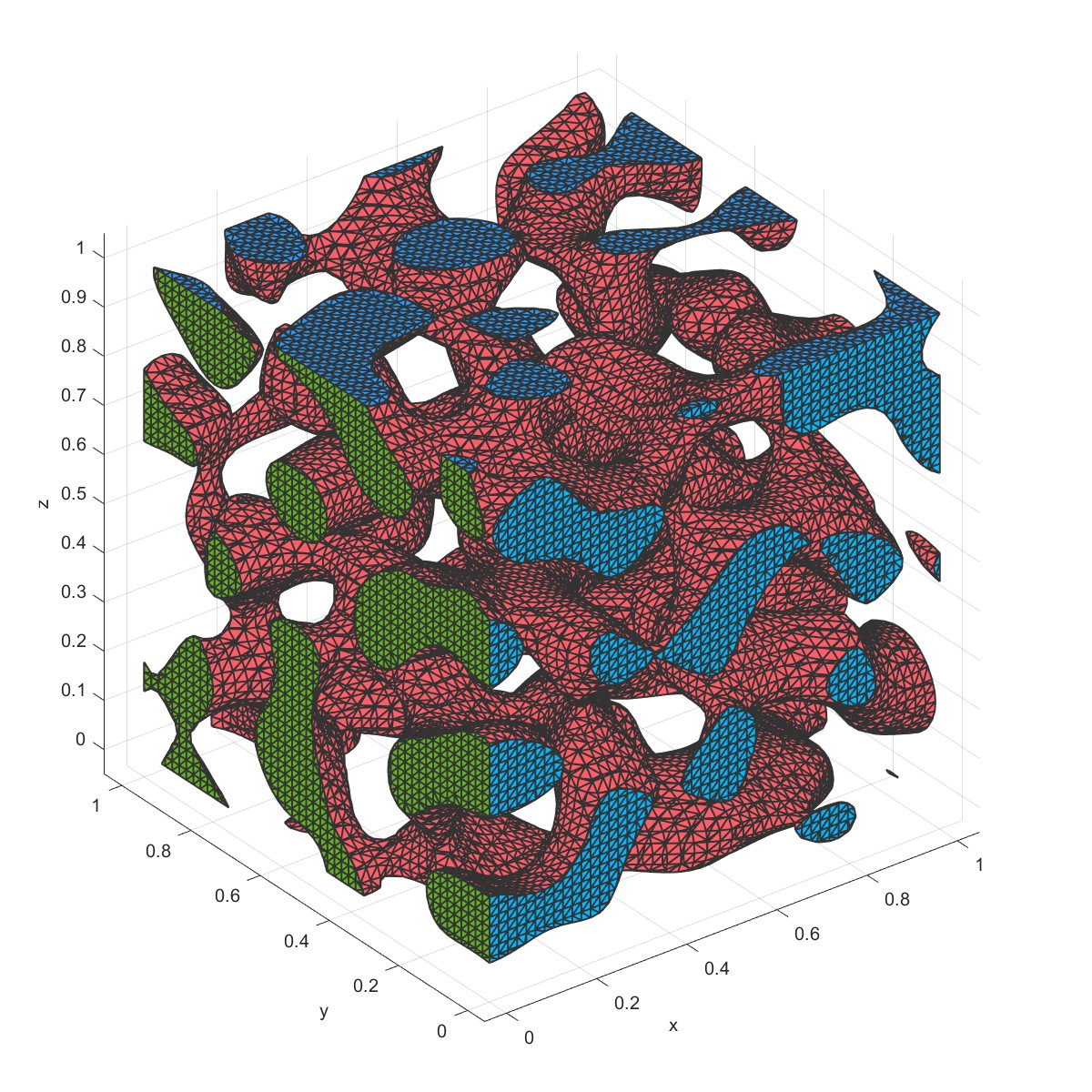
Mesh StochasticMicroStructure (Flag=9)
%Stochastic structure
Length=10; % Length of the sample
paticleLength=1;
mm=Mesh('Demo Stochastic structure Mesh');
mm=MeshStochasticMicroStructure(mm,Length,paticleLength);
PlotFace(mm);
建立微观元胞:
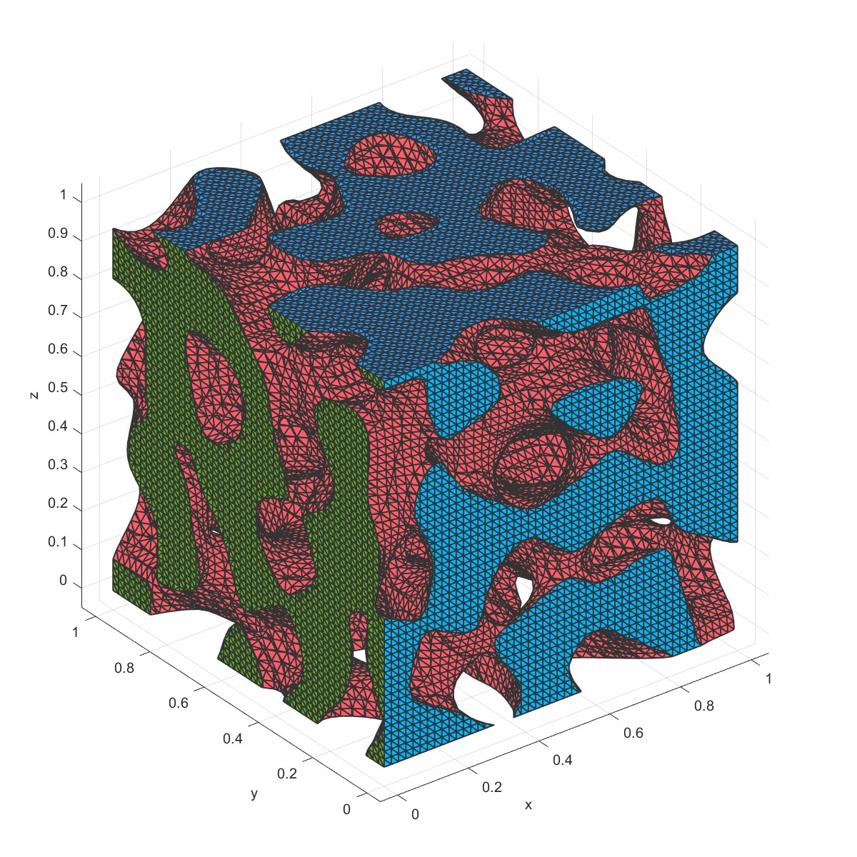
Mesh Spinodoid (Flag=10)
%spinodoid
Length=10; % Length of the sample
paticleLength=1;
mm=Mesh('Demo spinodoid Mesh');
mm=MeshSpinodoid(mm,Length,paticleLength);
PlotFace(mm);
建立微观元胞:
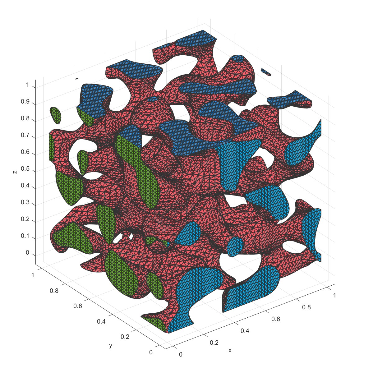
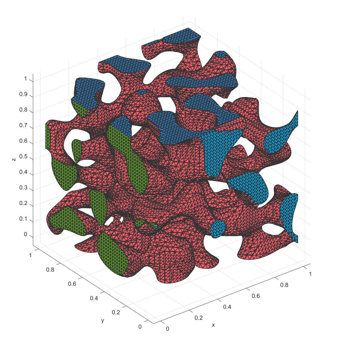
Group Test (Flag=11)
%Stochastic structure
Length=10; % Length of the sample
paticleLength=1;
mm=Mesh('Demo Stochastic structure Mesh');
mm=MeshStochasticMicroStructure(mm,Length,paticleLength);
PlotFace(mm);
[G,~]=GroupTest(mm);
disp(G);
mm=KeepGroup(mm,1);
PlotFace(mm);
用Group Test找到独立的网格,并保留其中一块独立的区域:
 |  |
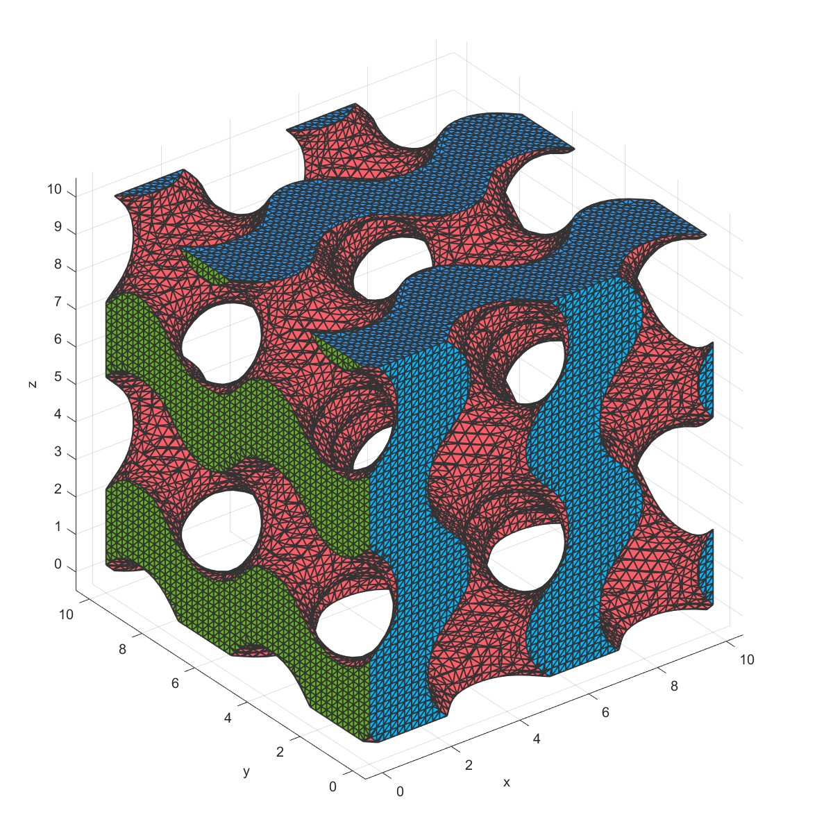
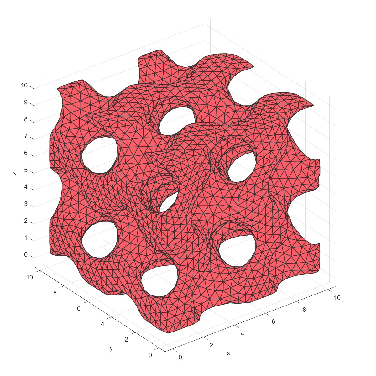
Remesh (Flag=12)
%Gyroid
Length=10; % Length of the sample
mm=Mesh('Demo Gyroid Mesh');
mm=MeshTriplyPeriodicMinimalSurface(mm,Length);
PlotFace(mm);
mm=Remesh(mm,0.5);
PlotFace(mm);
网格重新绘制:
 |  |
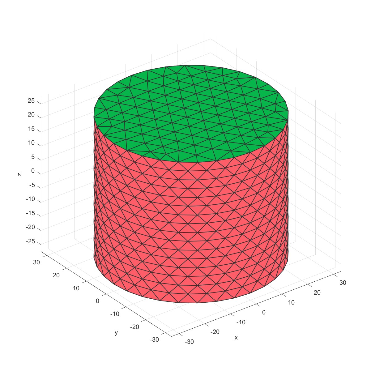
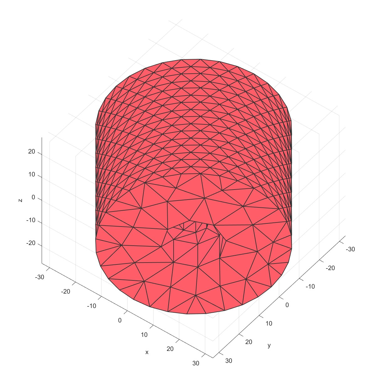
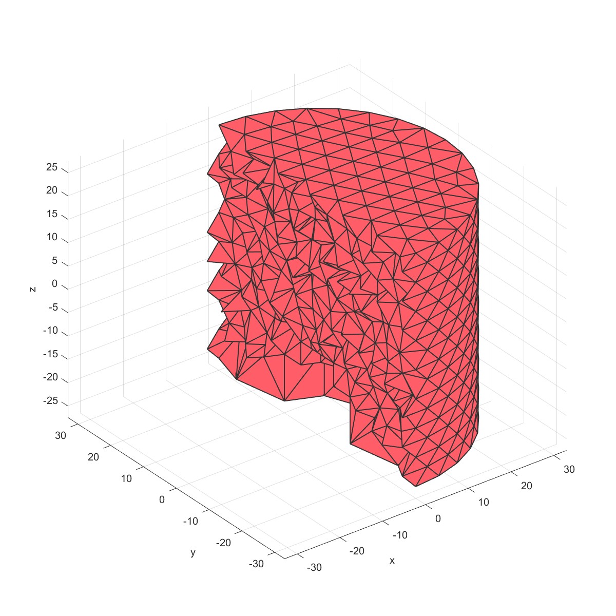
Drill holes (Flag=13)
% Derive patch data for a cylinder
mm=Mesh('Cylinder Mesh');
mm=MeshCylinder(mm,3,30,50);
PlotFace(mm);
% The cyclinder is meshed using tetrahedral elements using tetgen
mm=Mesh3D(mm); % Mesh model using tetrahedral elements using tetGen
sec.pos=[0,0,0];
sec.vec=[1,0,0];
PlotElement(mm,'section',sec);
mm=DrillHole(mm,[10;5],[10;15],[0,0],3,'type',5,'slice',8);
mm=Mesh3D(mm); % Mesh model using tetrahedral elements using tetGen
PlotFace(mm);
sec.pos=[0,0,0];
sec.vec=[1,0,0];
PlotElement(mm,'section',sec);
在指定的面上钻盲孔,并且可定义盲孔的尺寸。
 |  |
 |  |
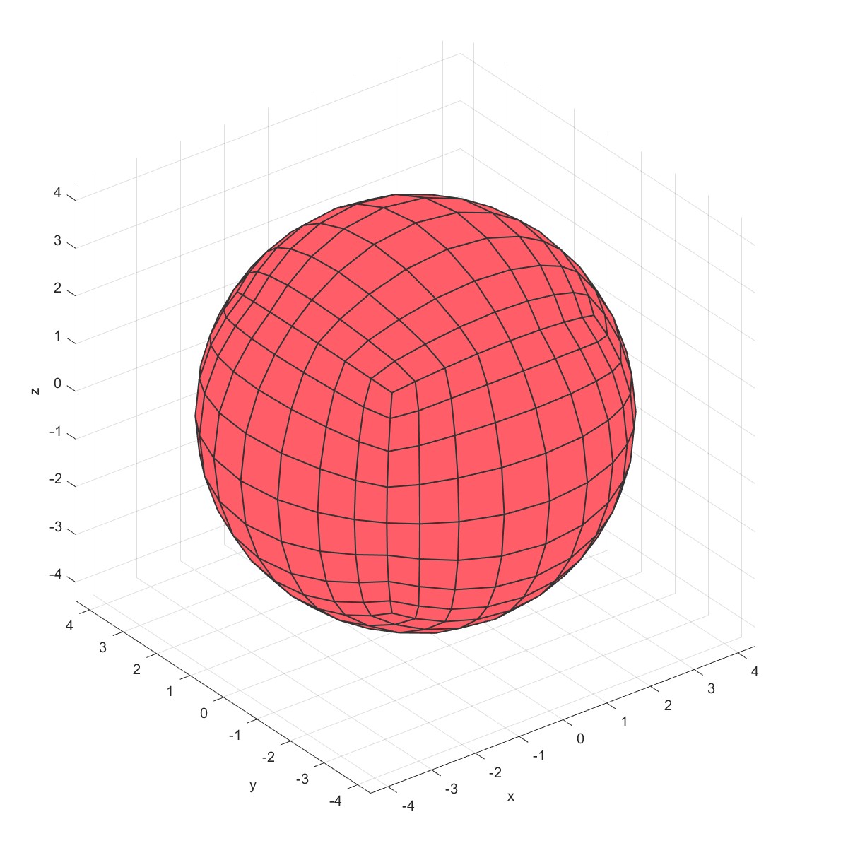
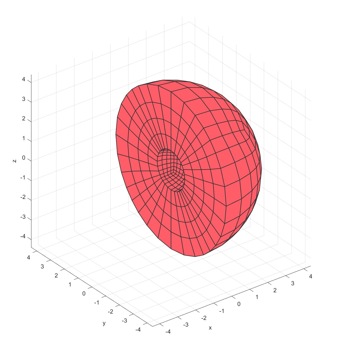
MeshQuadSphere (Flag=14)
%Sphere parameters
numRefineStepsSphere=4;
sphereRadius=4;
mm=Mesh('Demo Quad Sphere Mesh');
mm=MeshQuadSphere(mm,numRefineStepsSphere,sphereRadius);
PlotFace(mm);
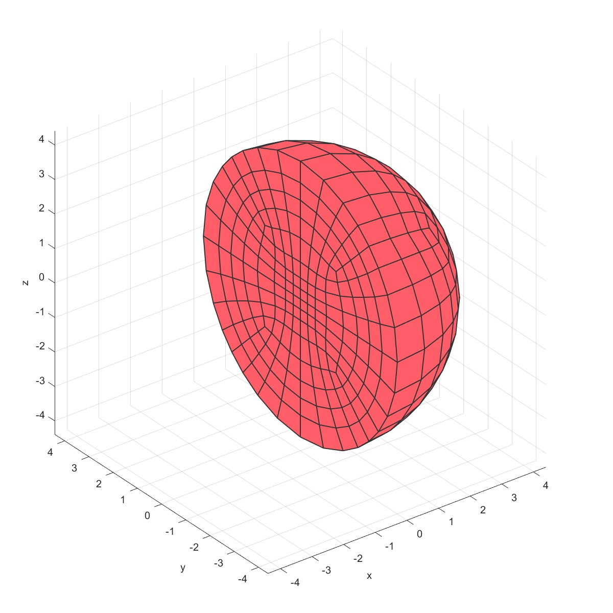
sec.pos=[0,0,0];
sec.vec=[1,0,0];
PlotElement(mm,'section',sec);
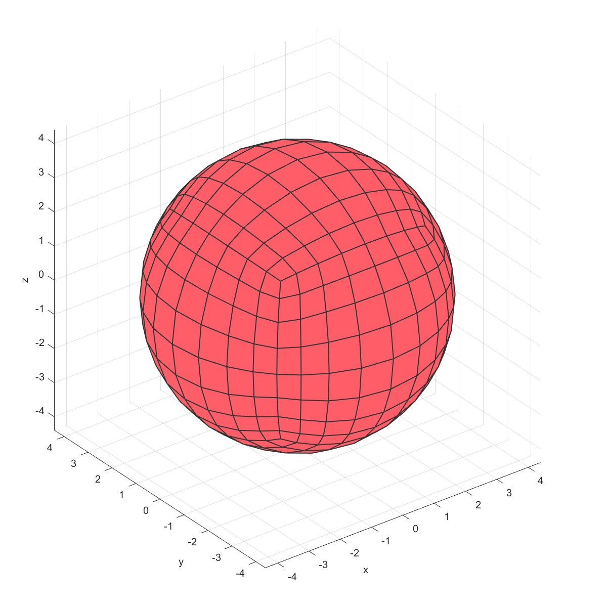
mm1=Mesh('Demo Quad hollow Sphere Mesh');
mm1=MeshQuadSphere(mm1,numRefineStepsSphere,sphereRadius,'hollow',1,'coreRadius',sphereRadius/4);
PlotFace(mm1);
PlotElement(mm1,'section',sec);
绘制六面体圆网格。
 |  |
 |  |
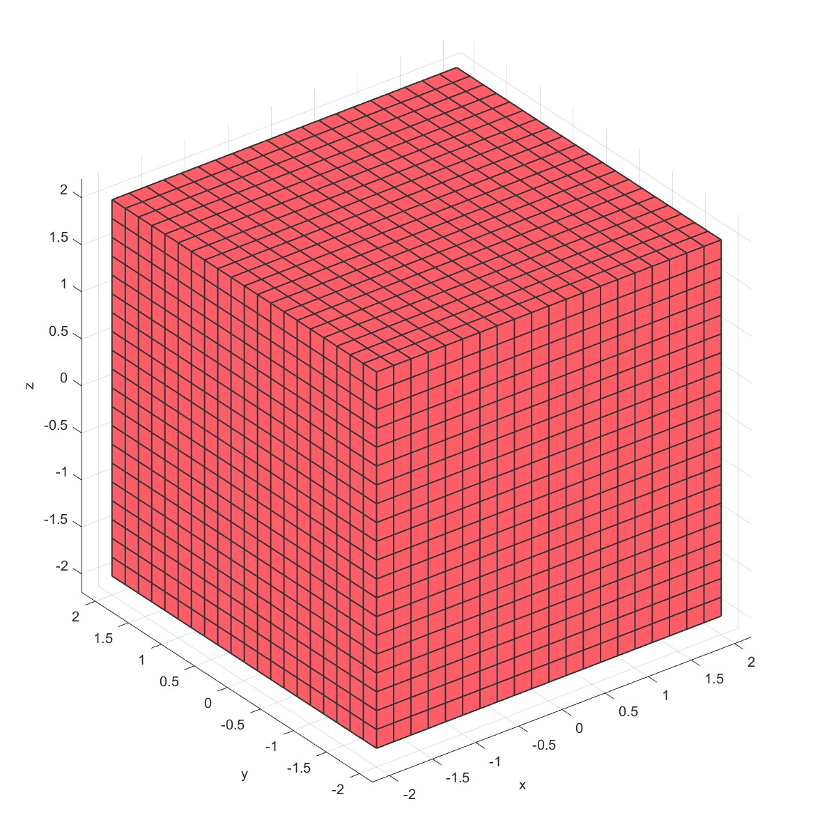
Mesh TensorGrid (Flag=15)
x = linspace(-2,2,21);
mm=Mesh('Demo TensorGrid');
mm=MeshTensorGrid(mm,x,x,x);
PlotFace(mm);
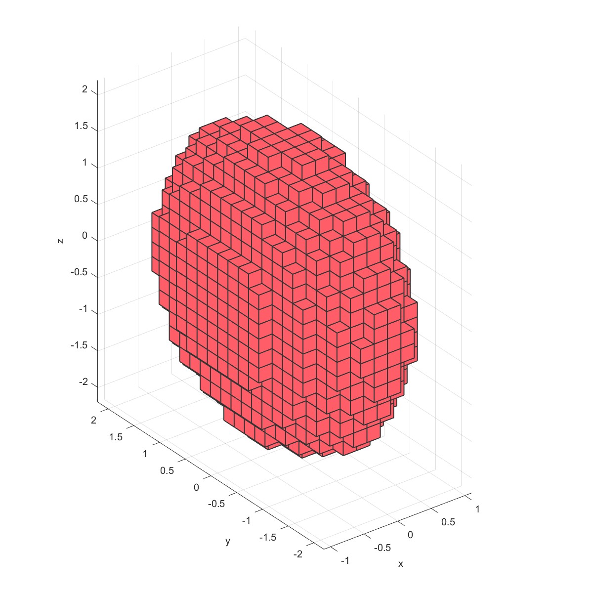
mm= ComputeGeometryG(mm);
c = mm.G.cells.centroids;
r = c(:,1).^2 + 0.25*c(:,2).^2+0.25*c(:,3).^2;
mm = RemoveCells(mm, r>1);
PlotFace(mm);
 |  |
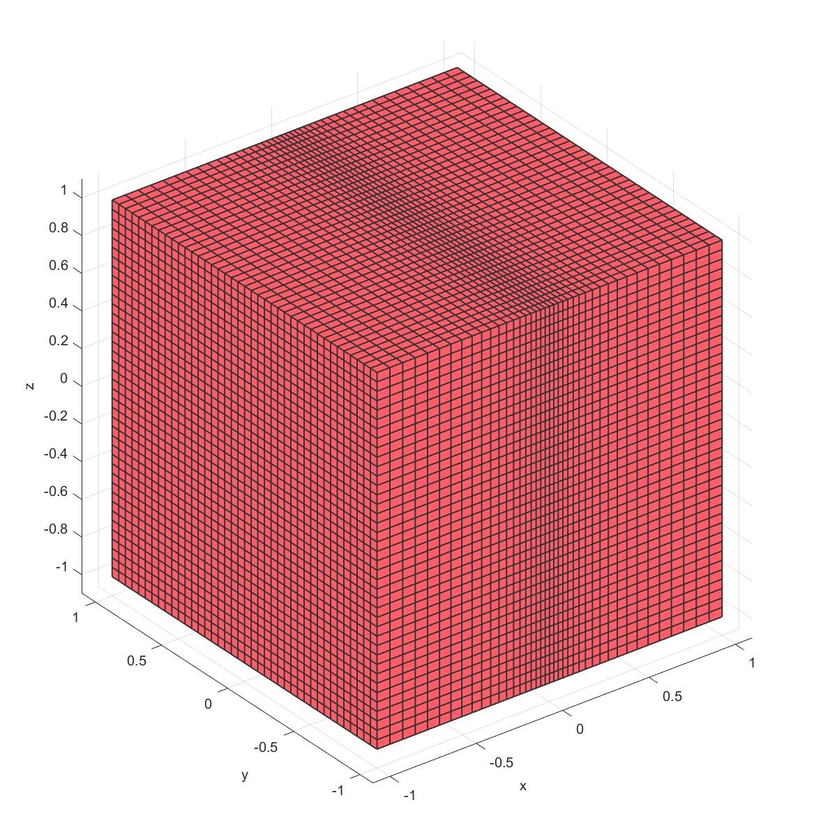
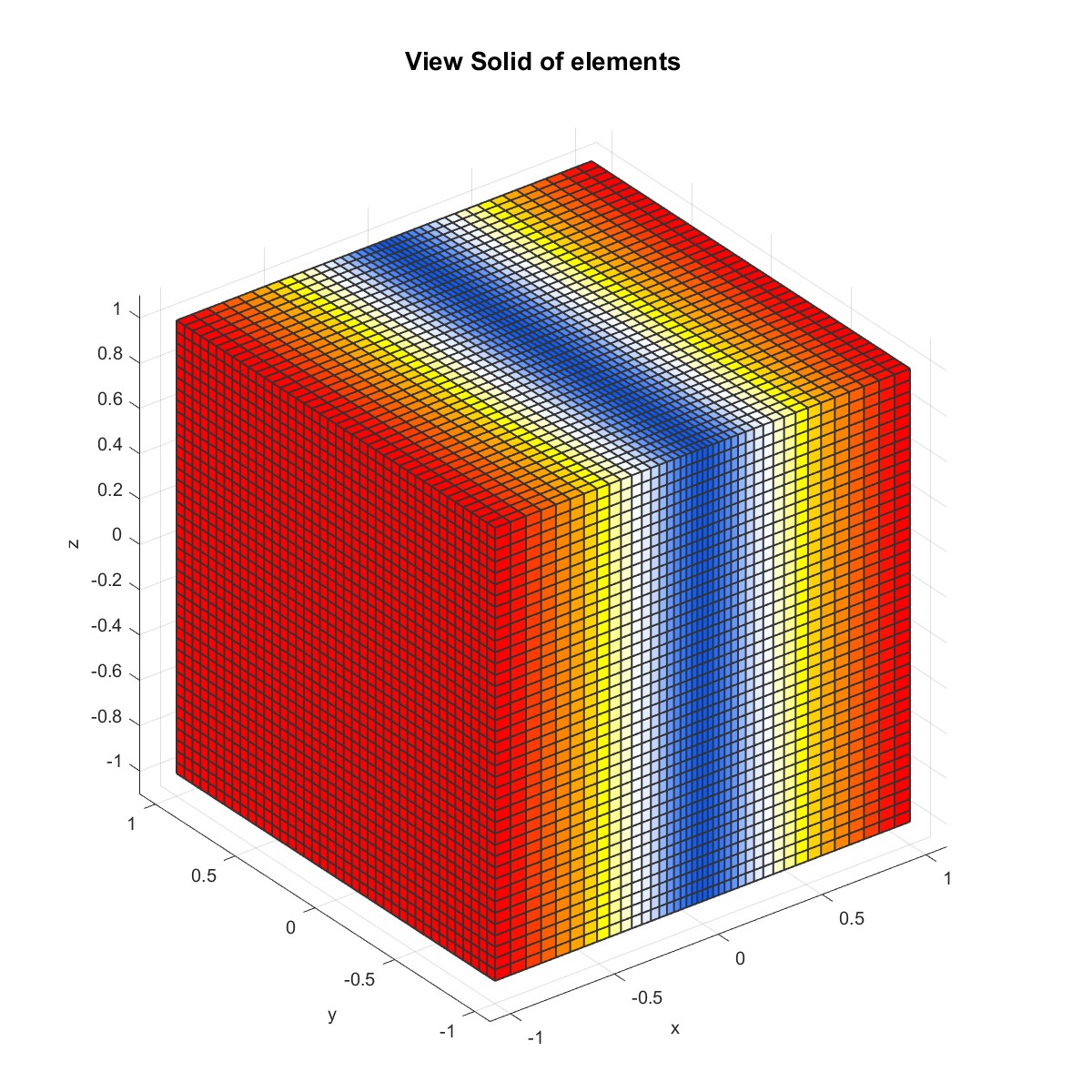
PlotG (Flag=16)
x=-1:0.05:1;
xx=x-1/2/pi.*sin(pi.*x);
yy=-1:0.05:1;
zz=-1:0.05:1;
mm=Mesh('Demo TensorGrid');
mm=MeshTensorGrid(mm,xx,yy,zz);
PlotFace(mm);
mm= ComputeGeometryG(mm);
PlotG(mm,'volume',1);
 |  |
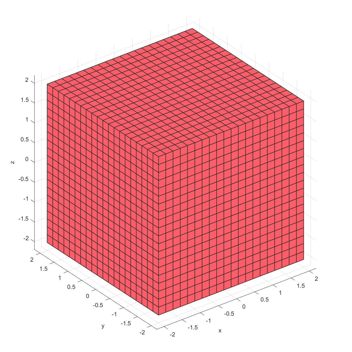
Simple sculpture Mesh (Flag=17)
x = linspace(-2,2,21);
mm=Mesh('Demo TensorGrid');
mm=MeshTensorGrid(mm,x,x,x);
PlotFace(mm);
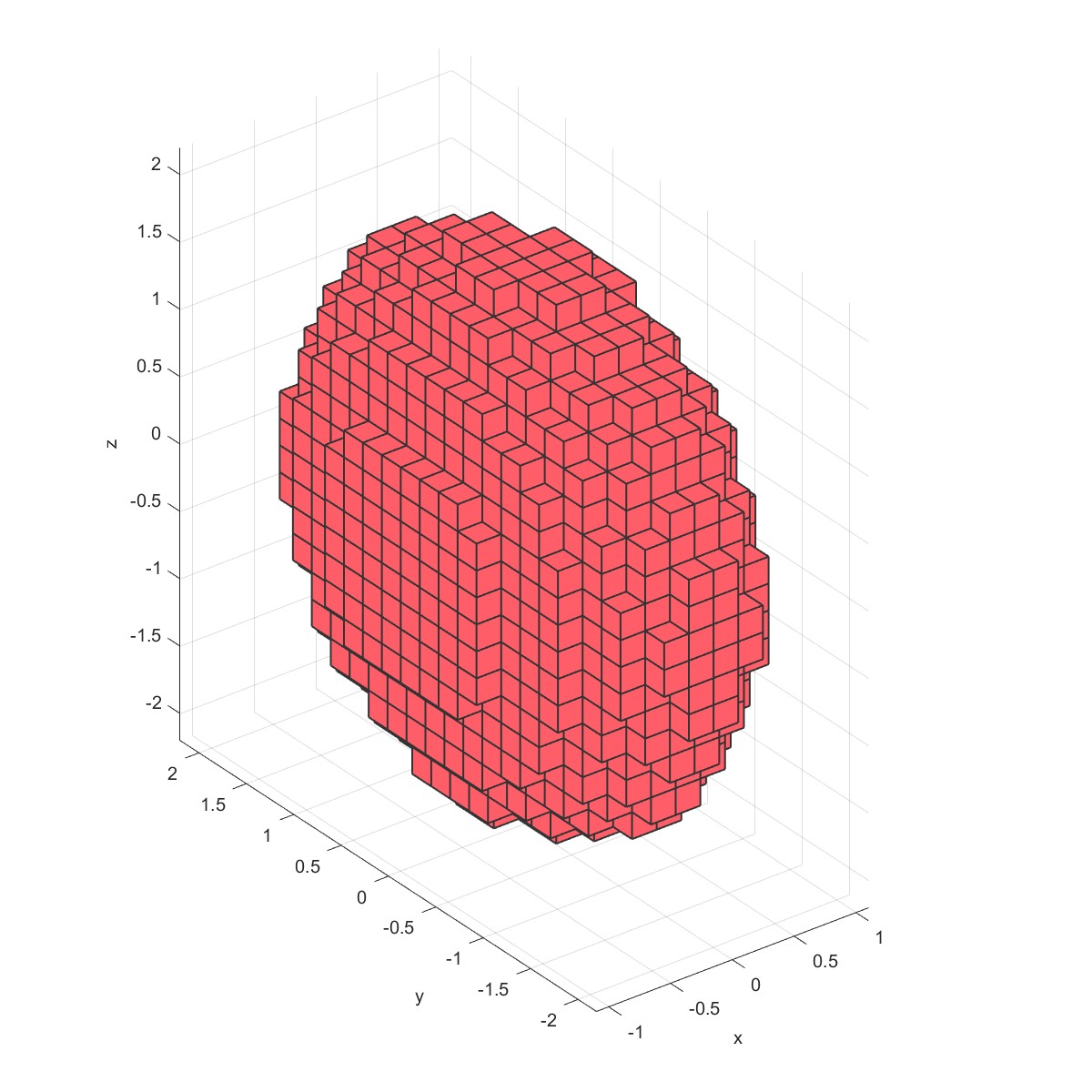
mm= ComputeGeometryG(mm);
c = mm.G.cells.centroids;
r = c(:,1).^2 + 0.25*c(:,2).^2+0.25*c(:,3).^2;
mm = RemoveCells(mm, r>1);
PlotFace(mm);
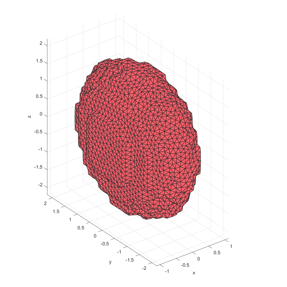
mm=Remesh(mm,0.2);
PlotFace(mm);
mm= Smoothface(mm,10);
mm=Mesh3D(mm);
PlotFace(mm);
sec.pos=[0,0,0];
sec.vec=[1,0,0];
PlotElement(mm,'section',sec);
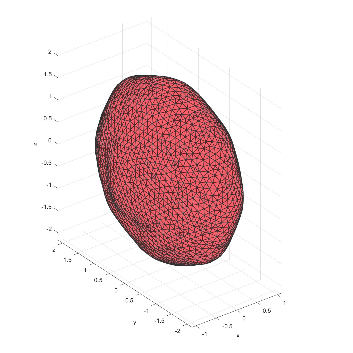
在六面体网格中雕刻出椭球体:
 |  |
 |  |

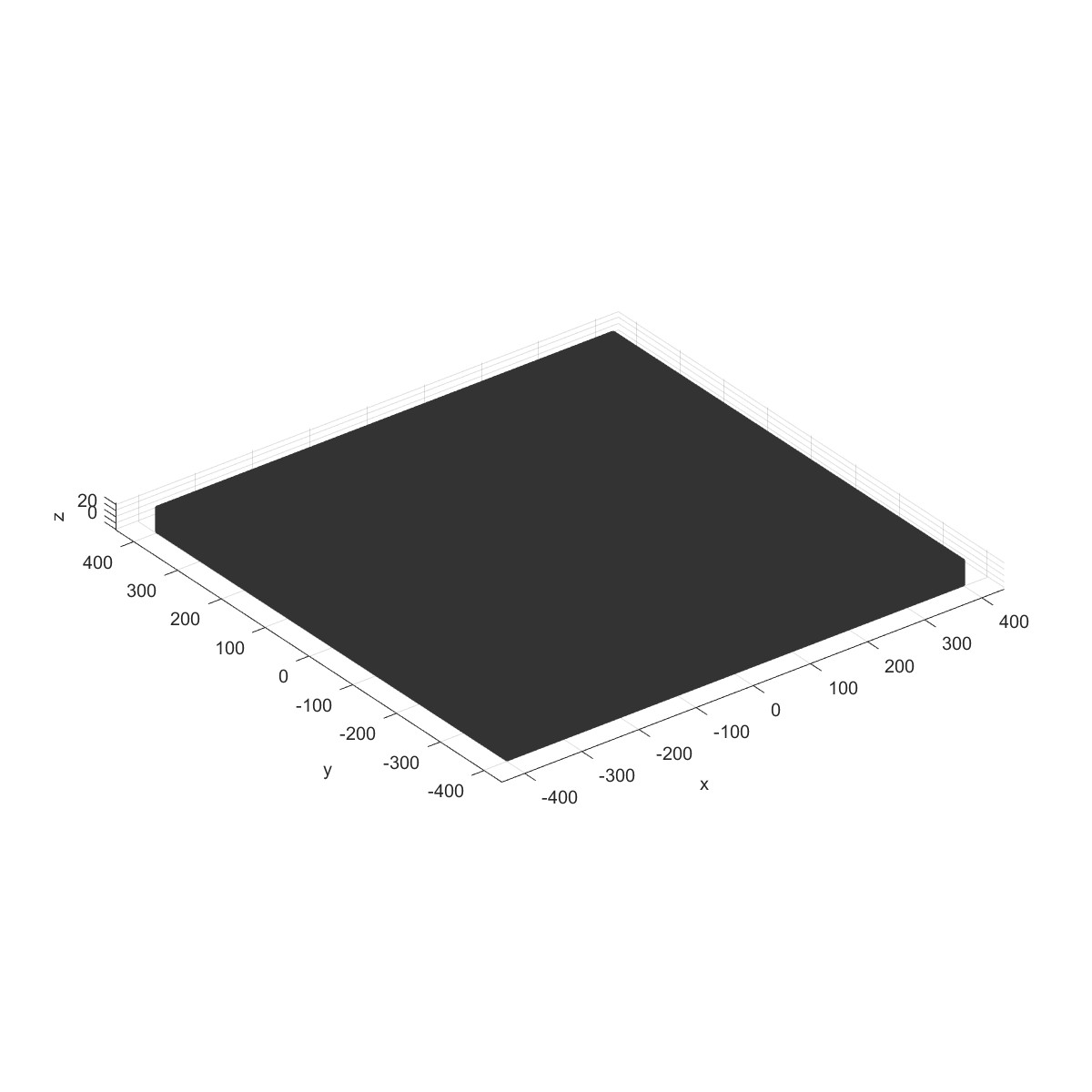
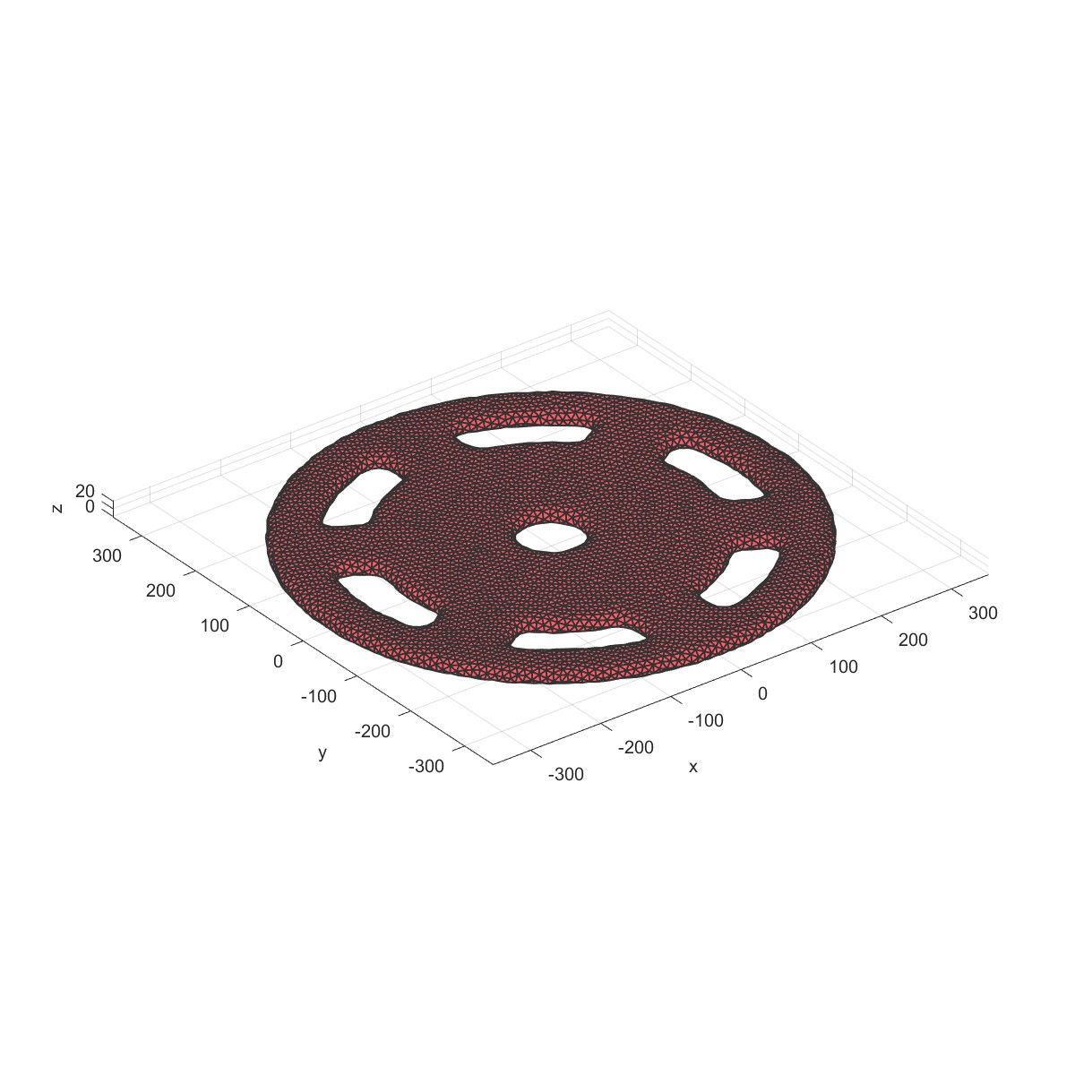
Check G center inner mesh (Flag=18)
% Original geometry
x = linspace(-400,400,200);
y=linspace(-400,400,200);
z=linspace(-10,30,40);
mm=Mesh('Demo TensorGrid');
mm=MeshTensorGrid(mm,x,y,z);
mm= ComputeGeometryG(mm);
PlotFace(mm);
% Plate
IR=80/2;
OR=650/2;
radius1=420/2;
radius2=520/2;
num=6;
par1=100;
Thickness=20;
ang1=360/num-asin(par1/2/radius1)/pi*180*2;
ang2=360/num-asin(par1/2/radius2)/pi*180*2;
a=Point2D('Point Ass1');
b=Line2D('Line Ass1');
a=AddPoint(a,0,0);
a=AddPoint(a,par1,0);
a=AddPoint(a,[radius1*cos(ang1/2/180*pi);radius2*cos(ang2/2/180*pi)],...
[radius1*sin(ang1/2/180*pi);radius2*sin(ang2/2/180*pi)]);
a=AddPoint(a,[radius2*cos(-ang2/2/180*pi);radius1*cos(-ang1/2/180*pi)],...
[radius2*sin(-ang2/2/180*pi);radius1*sin(-ang1/2/180*pi)]);
b=AddCircle(b,OR,a,1);
S=Surface2D(b);
h1=Line2D('Hole Group1');
h1=AddCircle(h1,IR,a,1);
S=AddHole(S,h1);
h2=Line2D('Hole Group2','Dtol',0.1);
h2=AddCircle(h2,radius1,a,1,'sang',-ang1/2,'ang',ang1);
h2=AddLine(h2,a,3);
h2=AddCircle(h2,radius2,a,1,'sang',ang2/2,'ang',-ang2);
h2=AddLine(h2,a,4);
h2=CreateRadius(h2,1,10);
h2=CreateRadius(h2,3,10);
h2=CreateRadius(h2,5,10);
h2=CreateRadius(h2,7,10);
for i=1:num
S=AddHole(S,h2,'rot',360/num*(i-1));
end
m=Mesh2D('Mesh1');
m=AddSurface(m,S);
m=SetSize(m,20);
m=Mesh(m);
Plot(m);
mm1=Mesh('Mesh');
mm1=Extrude2Solid(mm1,m,Thickness,3);
PlotFace(mm1);
% Check inner
in = IsInMesh(mm,mm1);
mm = RemoveCells(mm,~in);
PlotFace(mm);
mm=Remesh(mm,10);
PlotFace(mm);
mm= Smoothface(mm,10);
mm=Mesh3D(mm); % Mesh model using tetrahedral elements using tetGen
PlotFace(mm);
mm=Remesh(mm,10);
PlotFace(mm);
 |  |
MeshOctahedron (Flag=19)
dimension=[2,2,2];
mm1=Mesh('Mesh');
mm1=MeshOctahedron(mm1,dimension);
PlotFace(mm1);
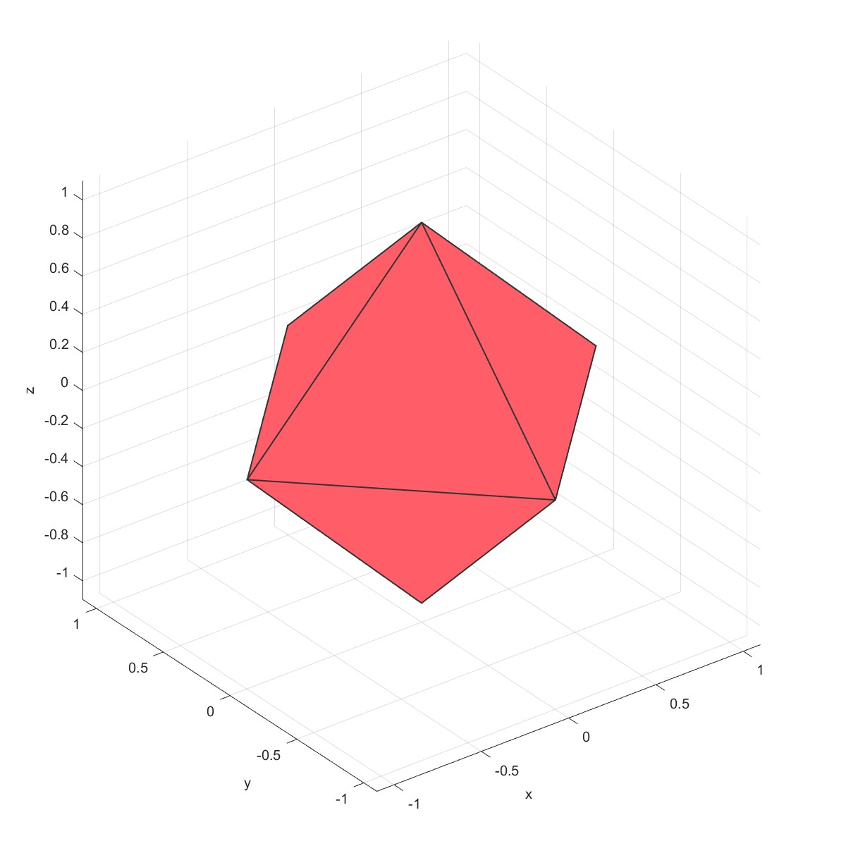
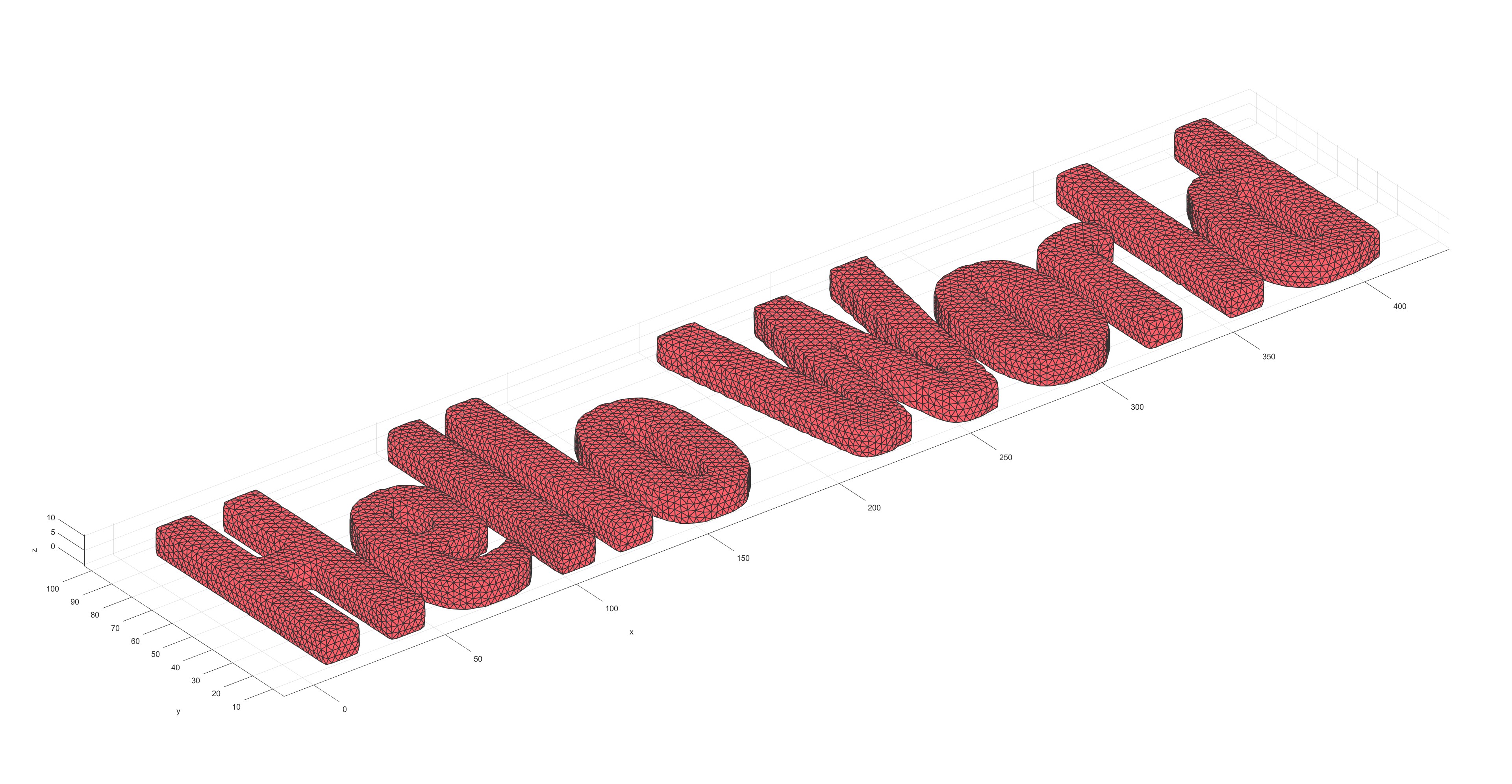
Image read (Flag=20)
hw=logical(imread('helloworld.png'));
imshow(hw);
m=Mesh2D('Mesh1');
nx=size(hw,2);ny=size(hw,1);
lx=size(hw,2)-1;ly=size(hw,1)-1;
m=MeshGrid(m,[nx, ny],[lx,ly]);
m= ComputeGeometryG(m);
PlotG(m);
m = RemoveCells(m,fliplr(hw'));
m = Quad2Tri(m);
PlotG(m);
mm=Mesh('Demo Hello World');
mm=Extrude2Solid(mm,m,10,3);
mm=Remesh(mm,5);
PlotFace(mm);
读取图片绘制网格:


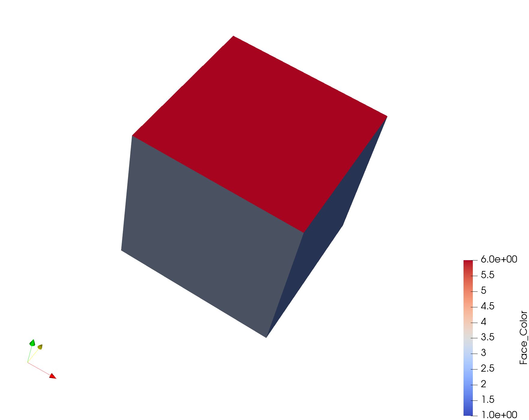
Plot Face in ParaView (Flag=21)
%% Specifying dimensions and number of elements
m=Mesh('Mesh');
%% Create a box with hexahedral elements
cubeDimensions=[10 10 10]; %Dimensions
cubeElementNumbers=[5 5 5]; %Number of elements
m=MeshCube(m,cubeDimensions,cubeElementNumbers);
%% Plot Face
PlotFace2(m);
在paraview显示表面网格:
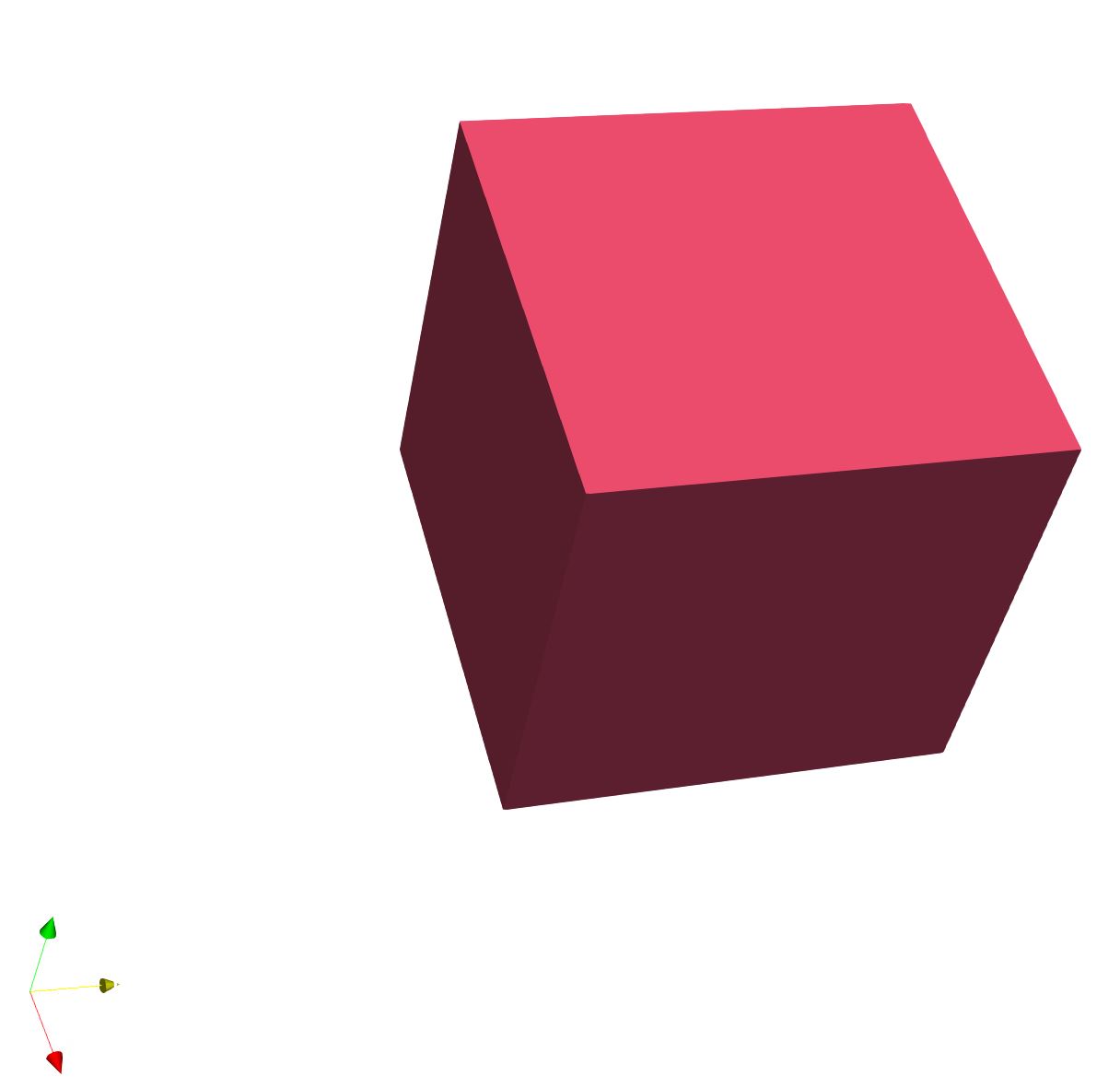
Plot Element in ParaView (Flag=22)
%% Specifying dimensions and number of elements
m=Mesh('Mesh');
%% Create a box with hexahedral elements
cubeDimensions=[10 10 10]; %Dimensions
cubeElementNumbers=[5 5 5]; %Number of elements
m=MeshCube(m,cubeDimensions,cubeElementNumbers);
%% Plot Element
PlotElement2(m)
在paraview中显示实体网格:
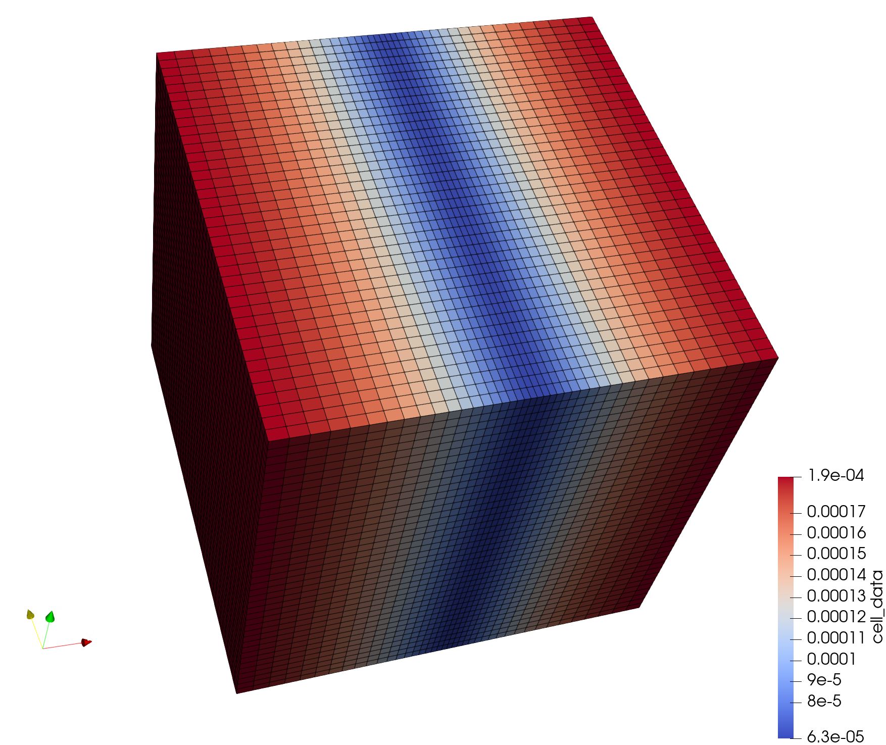
Plot G and cell data in ParaView (Flag=23)
x=-1:0.05:1;
xx=x-1/2/pi.*sin(pi.*x);
yy=-1:0.05:1;
zz=-1:0.05:1;
mm=Mesh('Demo TensorGrid');
mm=MeshTensorGrid(mm,xx,yy,zz);
PlotFace(mm);
mm= ComputeGeometryG(mm);
mm=AddCellData(mm,mm.G.cells.volumes);
PlotG2(mm);
在Mesh中加入celldata
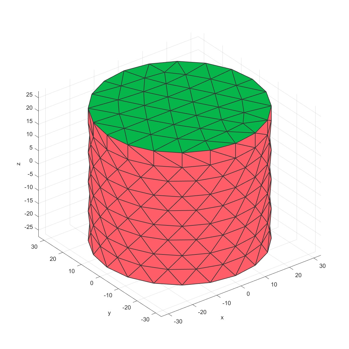
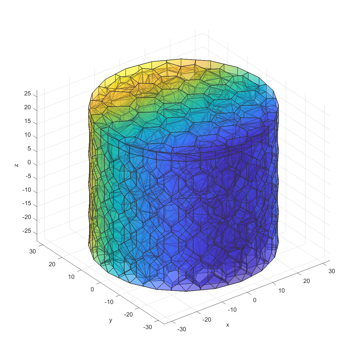
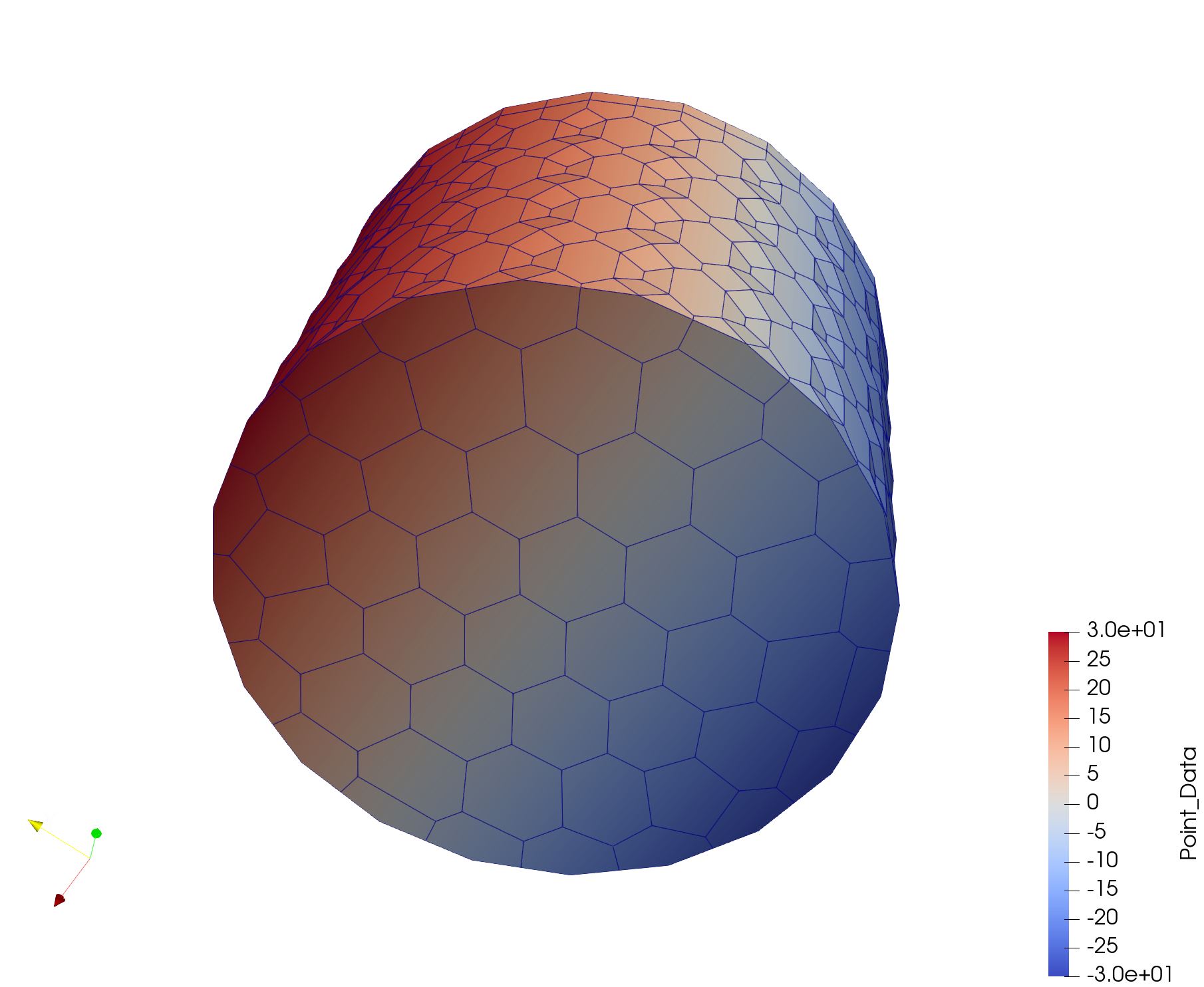
Tri3 to voronoi (Flag=24)
%Specifying dimensions and number of elements
mm=Mesh('Cylinder Mesh');
mm=MeshCylinder(mm,5,30,50);
PlotFace(mm);
% The cyclinder is meshed using tetrahedral elements using tetgen
mm=Mesh3D(mm); % Mesh model using tetrahedral elements using tetGen
mm=Tri2Voronoi(mm);
mm=AddPointData(mm,mm.Voronoi.Nodes(:,2));
PlotVoronoi(mm);
PlotVoronoi2(mm);
四面体网格转化为voronoi网格
 |  |
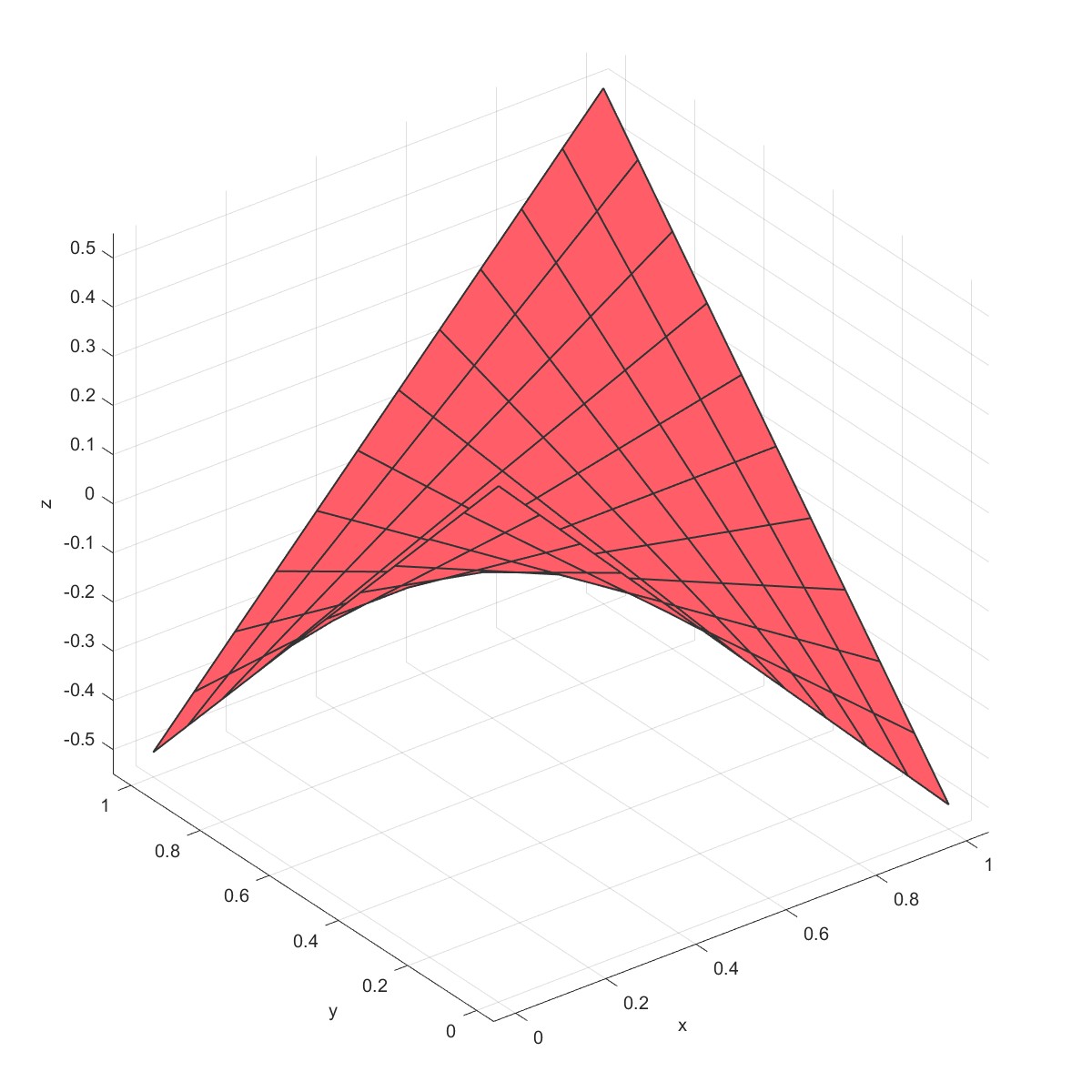
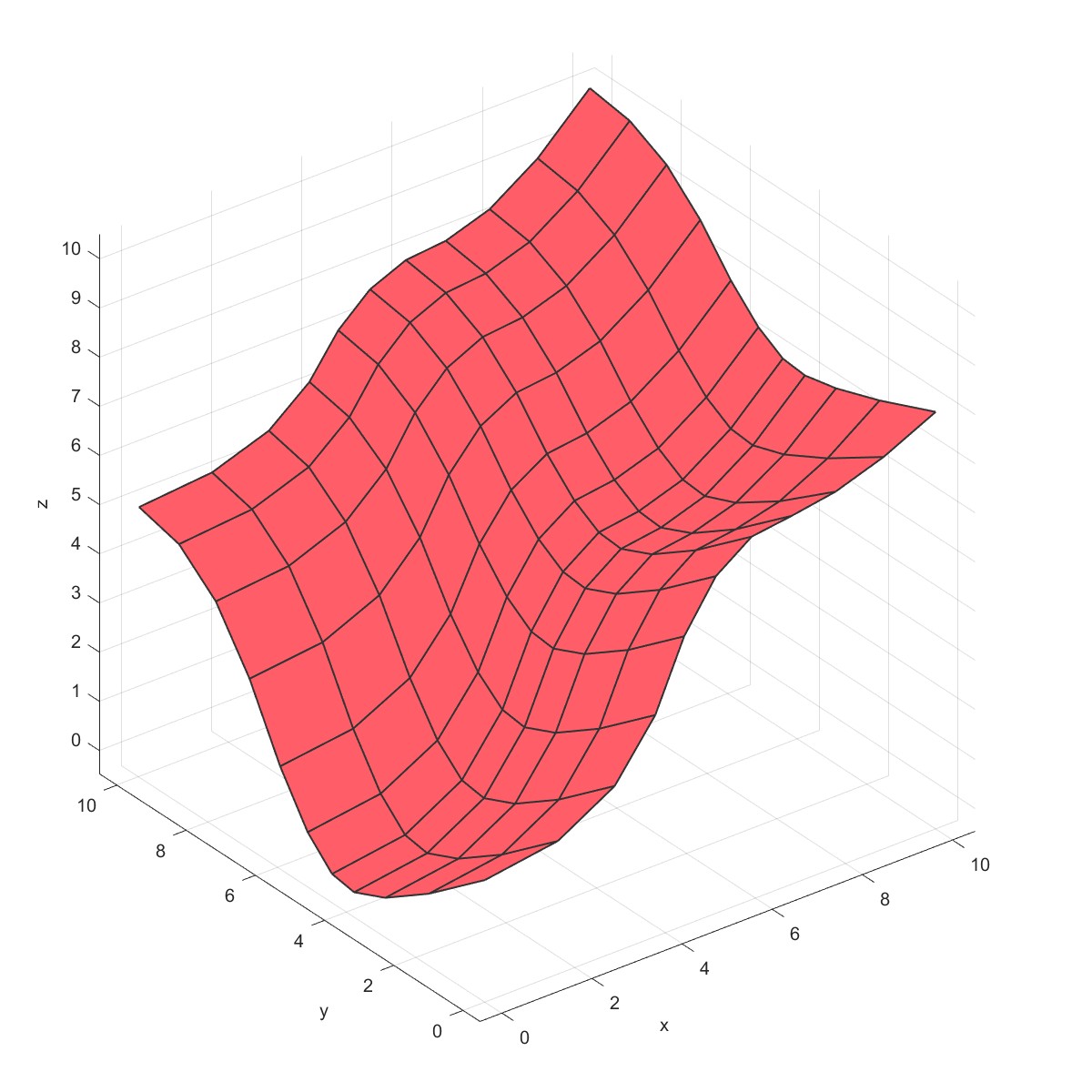
Nurb4Surf (Flag=25)
% Define 4 corner points of surface
mm=Mesh('Nurb surface');
Points=[0,0,0.5;1,0,-0.5;0,1,-0.5;1,1,0.5];
mm = Nurb4Surf(mm,Points,'subd',[11,10]);
PlotFace(mm);
Nurb Surface (Flag=26)
% allocate multi-dimensional array of control points
pnts = zeros(3,5,5);
% define a grid of control points
% in this case a regular grid of u,v points
% pnts(3,u,v)
%
pnts(:,:,1) = [ 0.0 3.0 5.0 8.0 10.0; % w*x
0.0 0.0 0.0 0.0 0.0; % w*y
2.0 2.0 7.0 7.0 8.0]; % w*z
pnts(:,:,2) = [ 0.0 3.0 5.0 8.0 10.0;
3.0 3.0 3.0 3.0 3.0;
0.0 0.0 5.0 5.0 7.0];
pnts(:,:,3) = [ 0.0 3.0 5.0 8.0 10.0;
5.0 5.0 5.0 5.0 5.0;
0.0 0.0 5.0 5.0 7.0];
pnts(:,:,4) = [ 0.0 3.0 5.0 8.0 10.0;
8.0 8.0 8.0 8.0 8.0;
5.0 5.0 8.0 8.0 10.0];
pnts(:,:,5) = [ 0.0 3.0 5.0 8.0 10.0;
10.0 10.0 10.0 10.0 10.0;
5.0 5.0 8.0 8.0 10.0];
% knots
knots{1} = [0 0 0 1/3 2/3 1 1 1]; % knots along u
knots{2} = [0 0 0 1/3 2/3 1 1 1]; % knots along v
mm=Mesh('Nurb surface');
mm = NurbSurf(mm,pnts,knots);
PlotFace(mm);
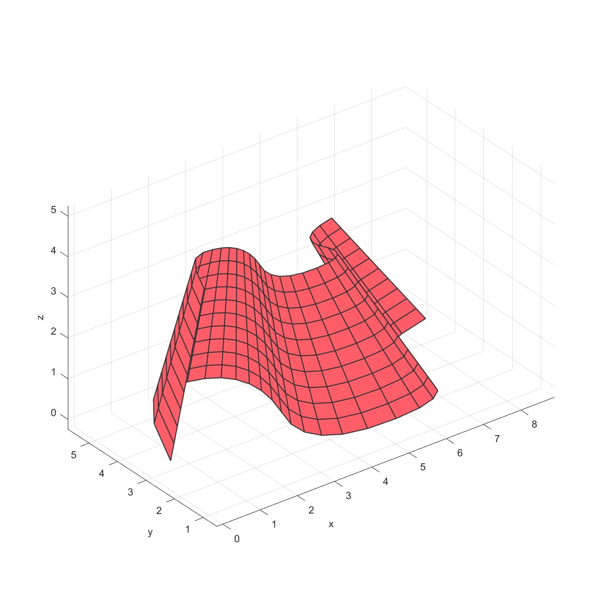
NurbRuled (Flag=27)
coefs = [0.5 1.5 4.5 3.0 7.5 6.0 8.5;
3.0 5.5 5.5 1.5 1.5 4.0 4.5;
0.0 0.0 0.0 0.0 0.0 0.0 0.0]';
knots=[0 0 0 1/10 2/5 3/5 4/5 1 1 1];
b=Line('Line Ass1');
b=AddNurb(b,coefs,knots);
b=Move(b,1,[0,0,5],'new',1);
b=Scale(b,2,[0.5,0.5,1]);
mm=Mesh('Nurb surface');
mm = NurbRuled(mm,b,1,2);
PlotFace(mm);
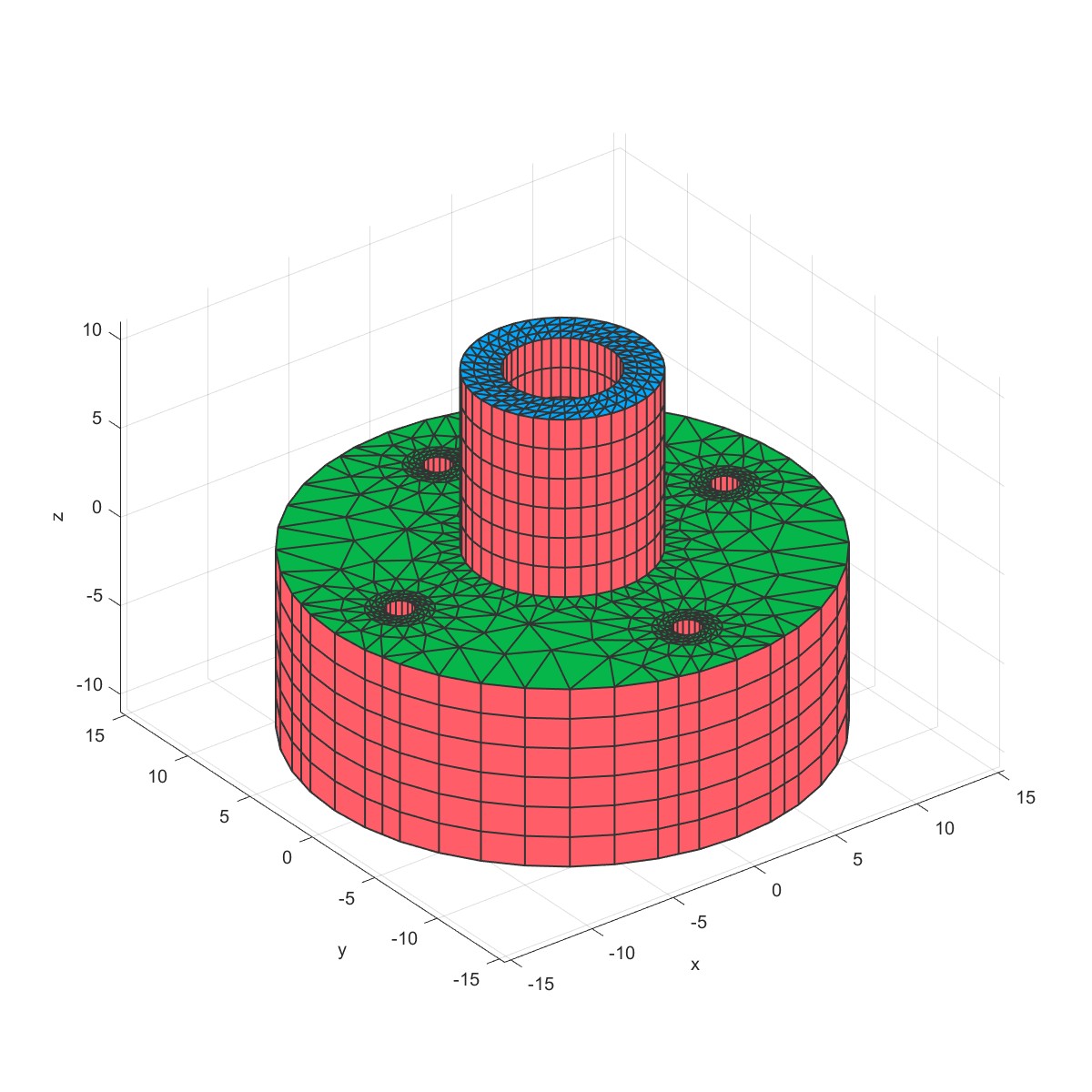
Extrude2Solid (Flag=28)
a=Point2D('Temp');
a=AddPoint(a,0,0);
% Add outline
b1=Line2D('Out');
b1=AddCircle(b1,14,a,1);
% Add innerline
b2=Line2D('Inner');
b2=AddCircle(b2,5,a,1,'seg',40);
% Add assembly hole
h=Line2D('Hole');
h=AddCircle(h,3.5/2,a,1,'seg',16);
S=Surface2D(b1);
S=AddHole(S,b2);
for i=1:4
S=AddHole(S,h,'dis',[10*cos(pi/2*(i-1)),10*sin(pi/2*(i-1))]);
end
m=Mesh2D('Temp');
m=AddSurface(m,S);
m=SetSize(m,5);
m=Mesh(m);
Plot(m)
% Mesh Layer edge
m=MeshLayerEdge(m,2,2);
% Mesh Layer edge
for i=3:6
m=MeshLayerEdge(m,2,1);
end
Plot(m)
mm=Mesh('Mesh1');
mm=Extrude2Solid(mm,m,-10,6);
PlotFace(mm);
mm=Extrude2Solid(mm,m,10,6,'Cb',2);
PlotFace(mm);
拉伸成体:
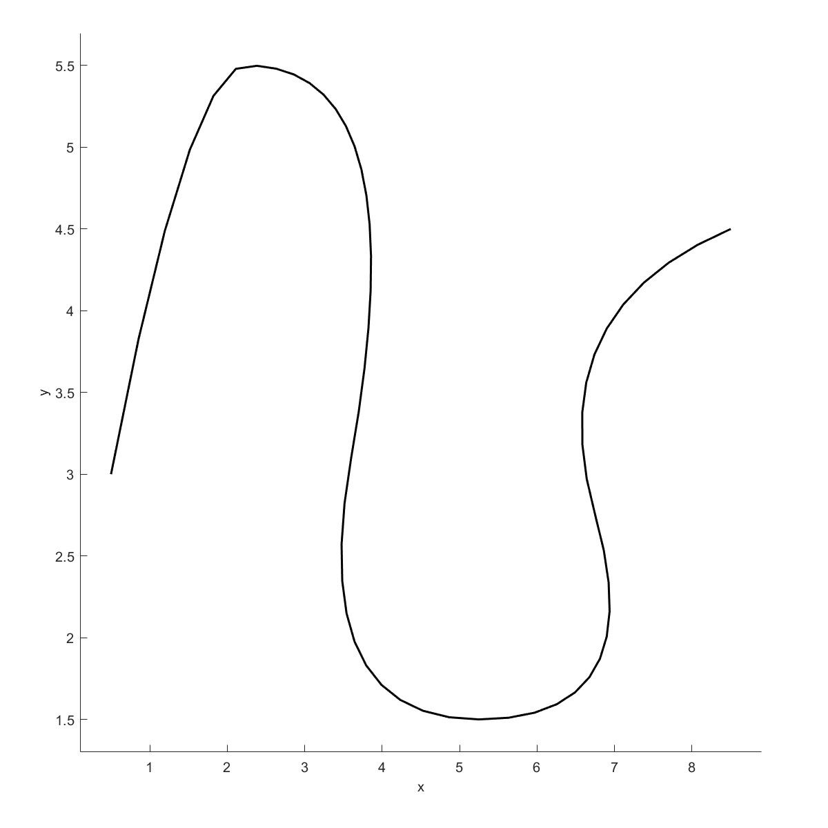
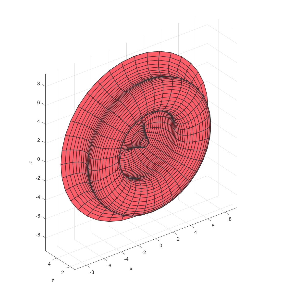
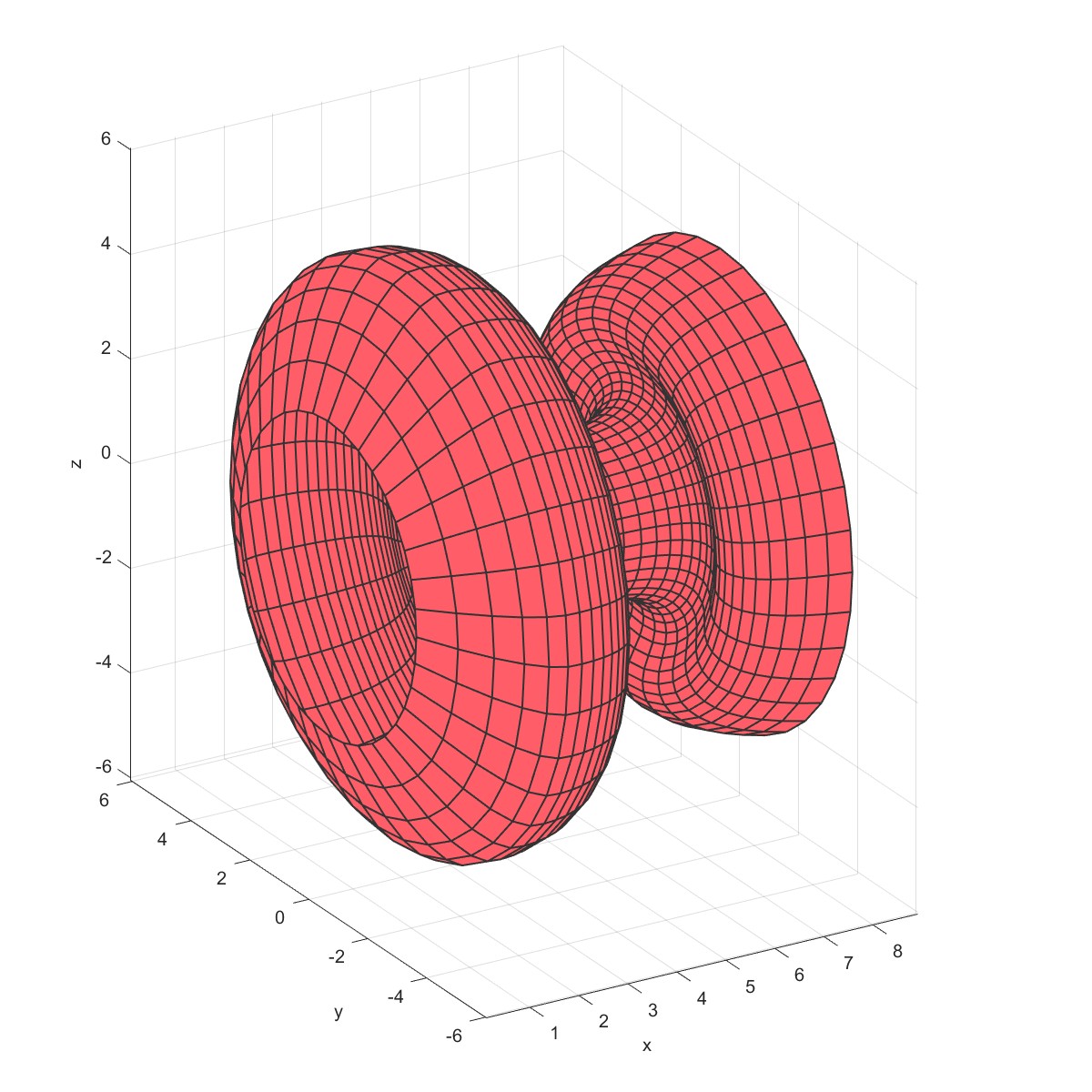
Rotate to shell (Flag=29)
Points = [0.5 1.5 4.5 3.0 7.5 6.0 8.5;
3.0 5.5 5.5 1.5 1.5 4.0 4.5]';
Knots=[0 0 0 1/10 2/5 3/5 4/5 1 1 1];
b=Line2D('Nurb Test');
b=AddNurb(b,Points,Knots);
Plot(b);
m1=Mesh('Mesh1');
m1=Rot2Shell(m1,b,'Type',2);
PlotFace(m1);
m2=Mesh('Mesh2');
m2=Rot2Shell(m2,b,'Type',1);
PlotFace(m2);
旋转成壳
 |  |
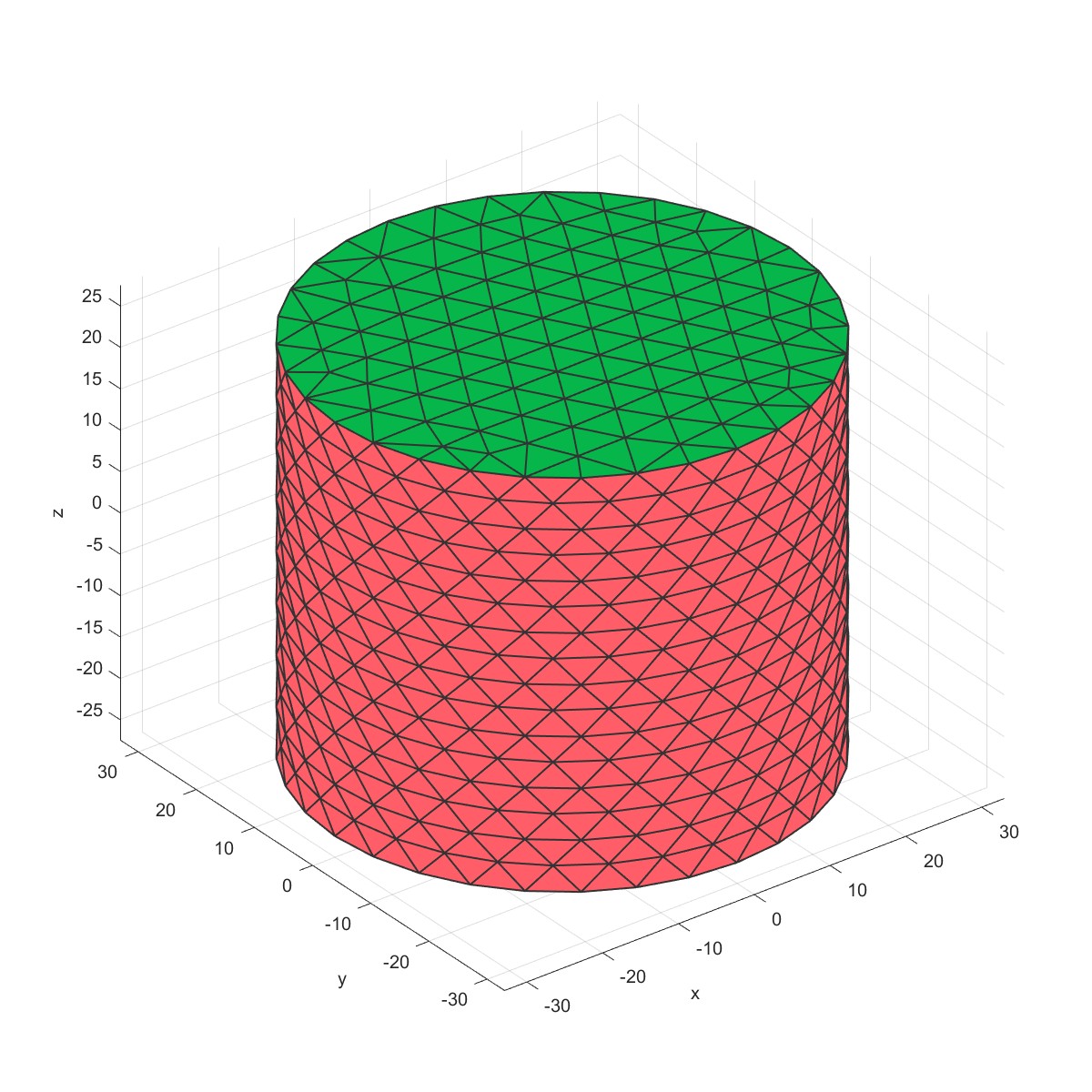
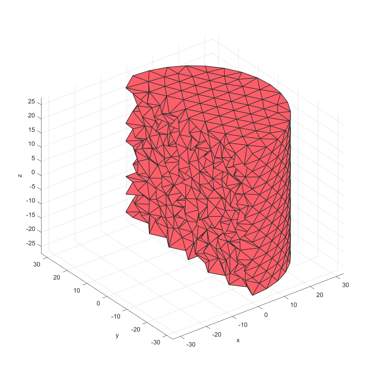
DrillThroughHole (Flag=30)
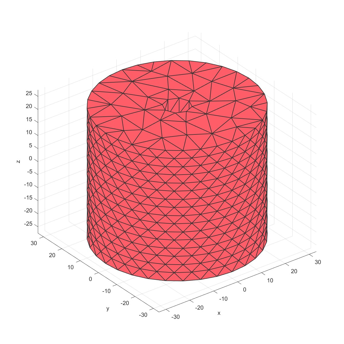
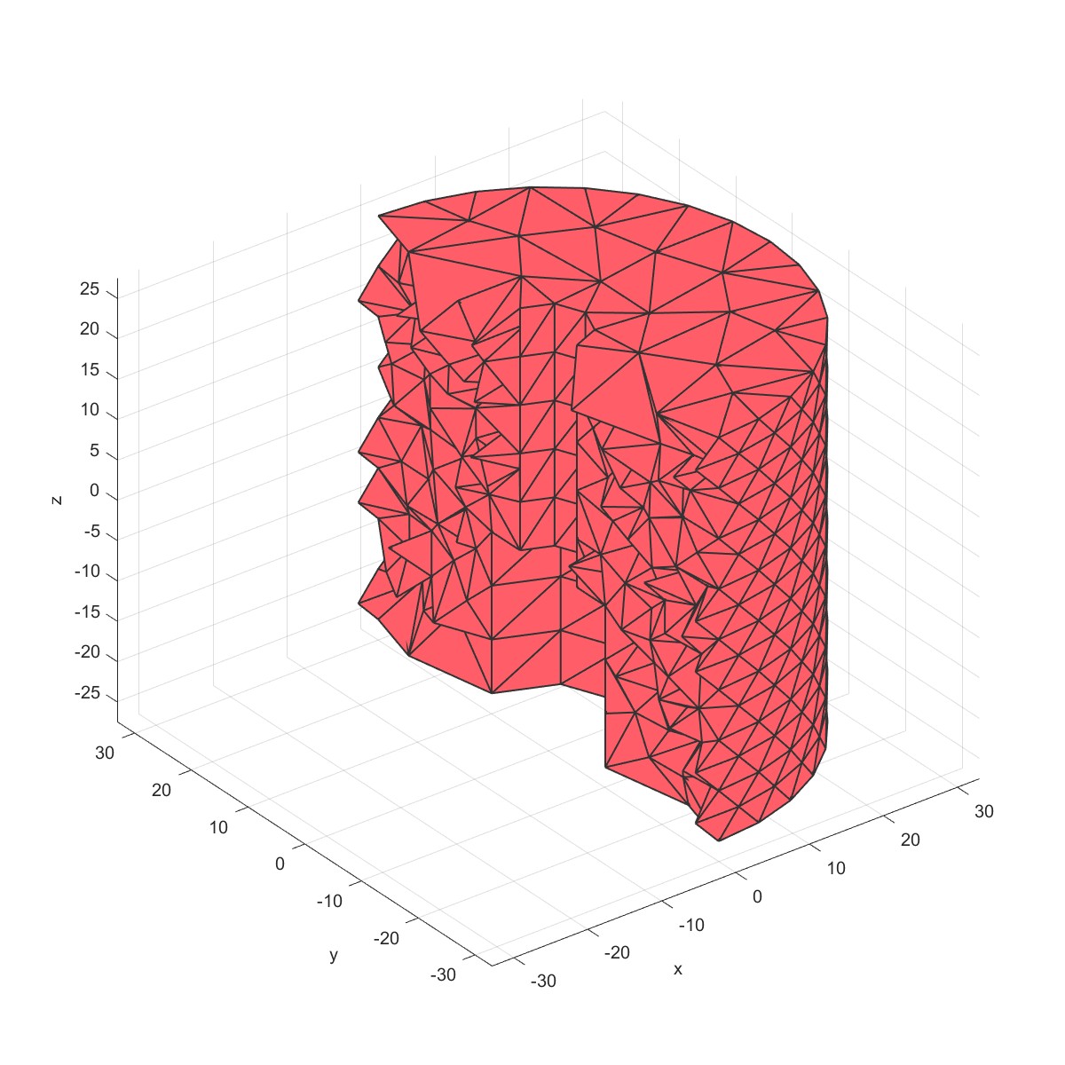
% Derive patch data for a cylinder
mm=Mesh('Cylinder Mesh');
mm=MeshCylinder(mm,3,30,50);
PlotFace(mm);
% The cyclinder is meshed using tetrahedral elements using tetgen
mm=Mesh3D(mm); % Mesh model using tetrahedral elements using tetGen
sec.pos=[0,0,0];
sec.vec=[1,0,0];
PlotElement(mm,'section',sec);
mm=DrillThroughHole(mm,[10;5],[20;50],[0,0],[3;2],'type',5,'slice',8);
mm=Mesh3D(mm); % Mesh model using tetrahedral elements using tetGen
PlotFace(mm);
sec.pos=[0,0,0];
sec.vec=[1,0,0];
PlotElement(mm,'section',sec);
网格开通孔。
 |  |
 |  |
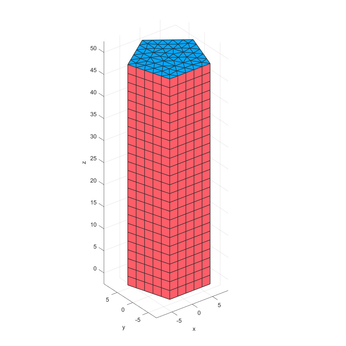
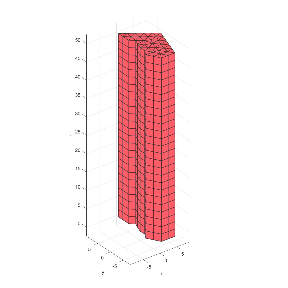
Mesh prism (Flag=31)
mm=Mesh('Prism Mesh');
mm=MeshPrism(mm,5,10,50);
PlotFace(mm);
sec.pos=[0,0,0];
sec.vec=[1,0,0];
PlotElement(mm,'section',sec);
棱柱网格。
 |  |
Mesh Geosphere (Flag=32)
mm=Mesh('Geosohere Mesh');
mm=MeshGeoSphere(mm,4,5,'Type',1);
PlotFace(mm);
mm=Mesh3D(mm);
sec.pos=[0,0,0];
sec.vec=[1,0,0];
PlotElement(mm,'section',sec);
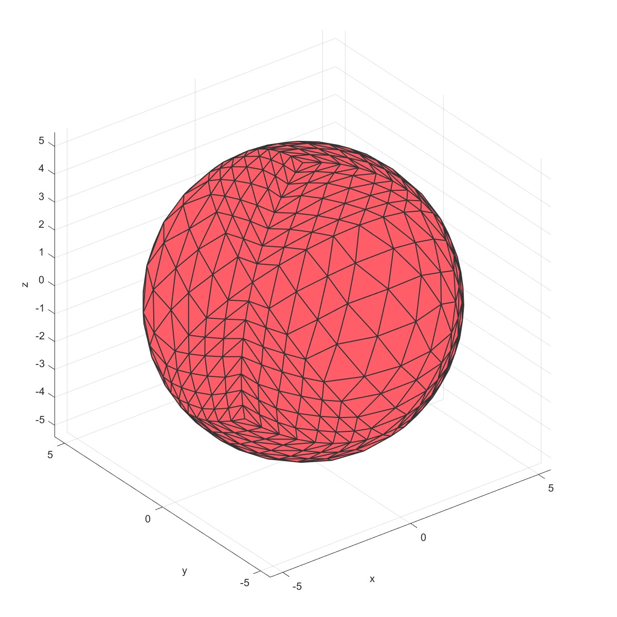 | 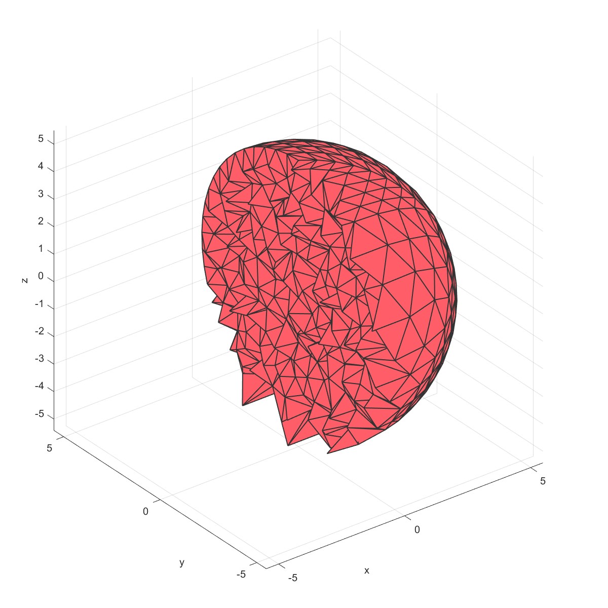 |
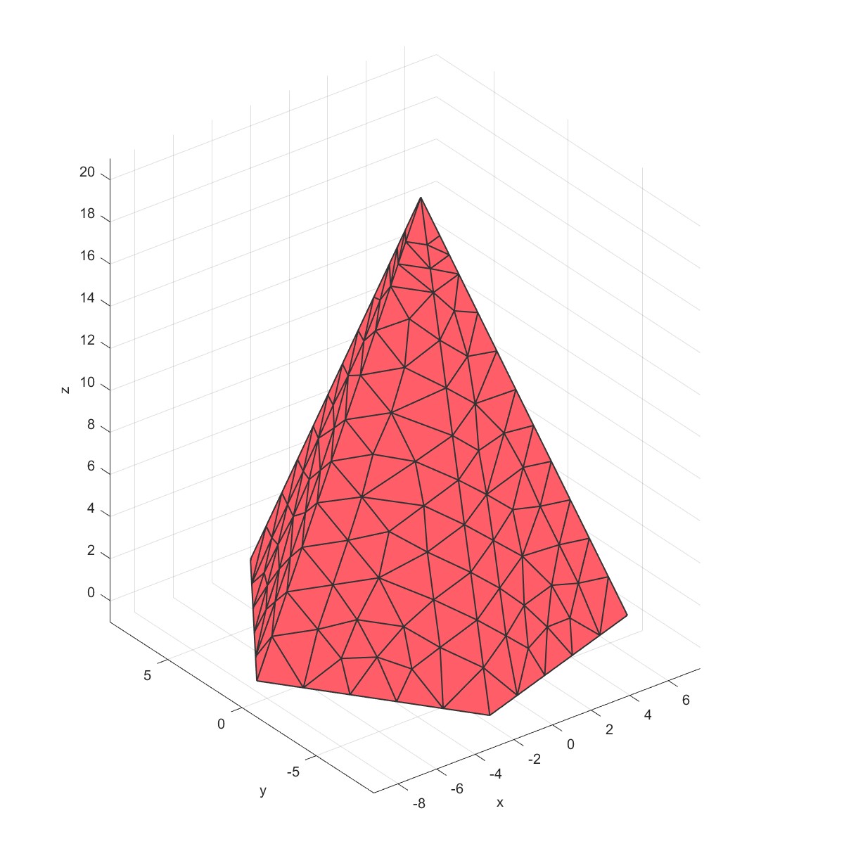
Mesh pyramid (Flag=33)
mm=Mesh('Pyramid Mesh');
mm=MeshPyramid(mm,5,10,20);
PlotFace(mm);
mm=Mesh3D(mm);
sec.pos=[0,0,0];
sec.vec=[1,0,0];
PlotElement(mm,'section',sec);
棱锥网格。
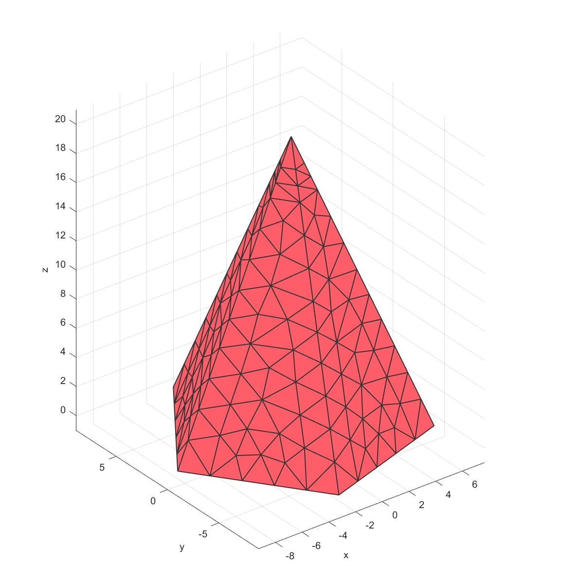 | 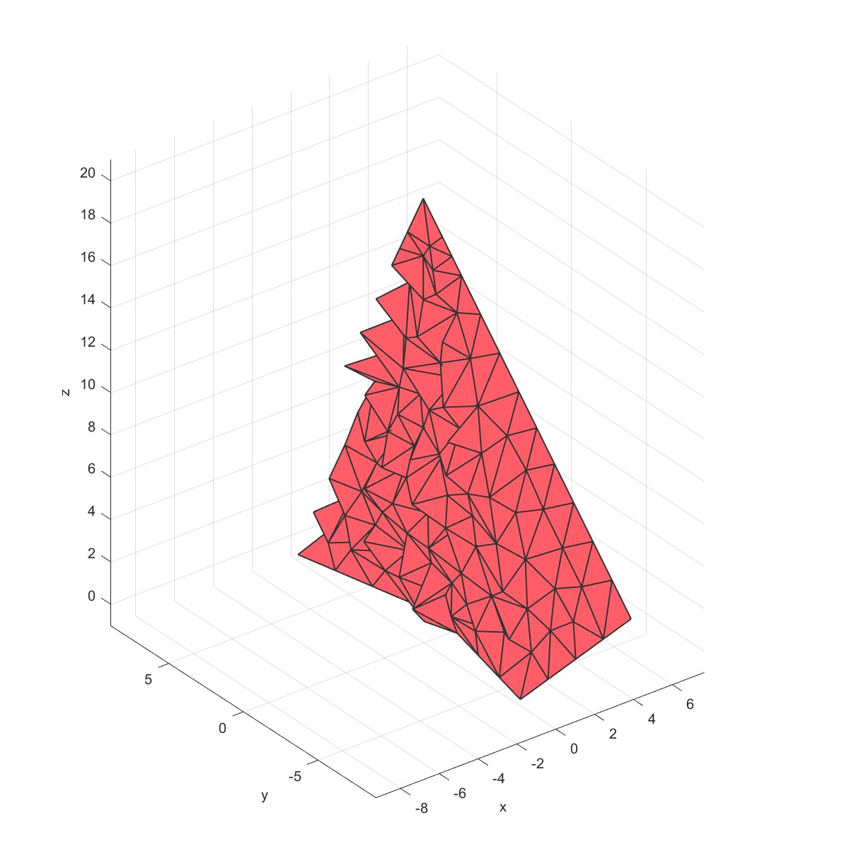 |
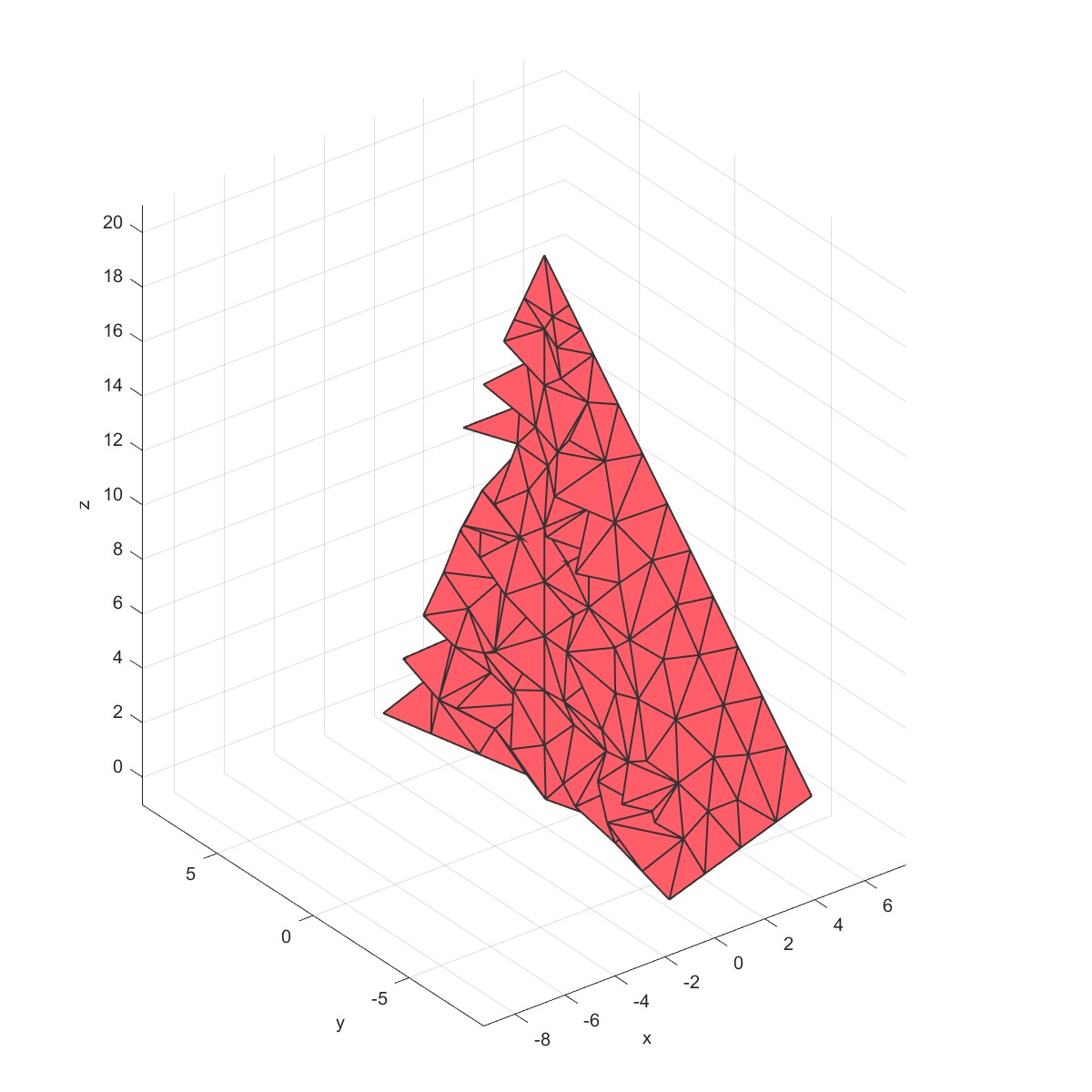
Add internal points (Flag=34)
mm=Mesh('Pyramid Mesh');
mm=MeshPyramid(mm,5,10,20);
PlotFace(mm);
mm=Mesh3D(mm,'AddedNodes',[0,0,2;0,0,4;0,0,6;0,0,8;0,0,10]);
sec.pos=[0,0,0];
sec.vec=[1,0,0];
PlotElement(mm,'section',sec);
再网格内部加约束点,划分网格时会以内部点为约束生成网格。
 |  |
CheatTable
| Name | Varargin | Description |
|---|---|---|
| AddCellData(obj,Data) | Add cell data to elements | |
| AddPointData(obj,Data) | Add point data to nodes | |
| AddPointVector(obj,Vec) | Add point vector to nodes | |
| CenterCal(obj) | Calculate center of elements | |
| Convert2Order2(obj) | Convert elements order | |
| DelNullElement(obj) | Delete null elements | |
| DrillHole(obj, radius,depth,position,faceno) |
‘type’, ‘slice’,’holetype’ | Drill holes on elements face |
| DrillThroughHole(obj, radius,depth,position,faceno) |
‘type’, ‘slice’,’holetype’ | Drill through holes on elements face |
| Extrude2Solid(obj,mesh2D,Height,Levels) | ‘Cb’ | Extrude 2D elements to 3D elements |
| FindBoundary(obj) | Find boundary of elements | |
| GetFaceNormal(obj) | Get elements face normal | |
| GroupTest(obj) | Test face group | |
| IsInMesh(obj,mesh) | Check geometry inner mesh face | |
| KeepGroup(obj,GroupNum) | Keep group and remove unused nodes | |
| MergeFaceNode(obj) | Merge face node | |
| Mesh3D(obj) | ‘stringOpt’, ‘minRegionMarker’ |
Create 3D meshes |
| MeshCube(obj, cubeDimensions,cubeElementNumbers) |
‘ElementType’, ,’outputStructType’, |
Mesh cube |
| MeshCylinder(obj,esize,Radius,Height) | ‘ElementType’,’close’ | Mesh cylinder |
| MeshHemiSphere(obj,Radius,MantelNum) | ‘coreRadius’, ‘outputStructType’, ‘hollow’,’smoothstep’ |
Create Hemi Sphere mesh |
| MeshOctahedron(obj,dimension) | Mesh octahedron | |
| MeshQuadSphere(obj,n,r) | ‘hollow’,’coreRadius’ | Mesh QuadSphere |
| MeshSphere(obj,n,r) | Mesh sphere | |
| MeshSpinodoid(obj,Length,paticleLength) | ‘Nw’,’WaveNum’,’relD’, ‘thetas’,’cap’ |
Mesh Spinodoid |
| MeshStochasticMicroStructure(obj, Length,paticleLength) |
‘Nw’,’q0’,’relD’, ‘anisotropy’,’cap’ |
Mesh Stochastic MicroStructure |
| MeshTensorGrid(obj,x,y,z) | Mesh tensor grid | |
| MeshTriplyPeriodicMinimalSurface(obj, length) |
‘cap’,’surfaceCase’, ‘numPeriods’,levelset’, |
Mesh Triply Periodic Minimal Surface |
| Nurb4Surf(obj,Points) | ‘subd’ | 4 points nurb surface |
| NurbRuled(obj,Points,crv1,crv2) | ‘subd’ | Nurb ruled |
| NurbSurf(obj,pnts,knots) | ‘subd’ | Nurb surface |
| PatchCentre(obj) | Get Center of Face boundary | |
| PlotElement(obj) | ‘grid’,’axe’,’equal’,’alpha’, ‘face_alpha’,’section’, ‘xlim’,ylim’,’zlim’,’view’ |
Plot element |
| PlotElement2(obj) | Plot elements in Paraview | |
| PlotFace(obj) | ‘grid’,’axe’,’equal’, ‘facecolor’,’alpha’, ‘face_alpha’,’face_normal’, ‘marker’, ‘xlim’,’ylim’,’zlim’, ‘view’ |
Plot Face of element |
| PlotFace2(obj) | Plot faces in Paraview | |
| PlotG(obj) | ‘grid’,’name’,’axe’,’equal’, ‘alpha’,’face_alpha’, ‘section’,’volume’ |
Plot mesh MRST G |
| PlotG2(obj) | Plot mesh MRST G in Paraview | |
| PlotVoronoi(obj) | ‘alpha’,’face_alpha’,’grid’, ‘equal’,’axe’,’marker’ |
Plot Voronoi |
| PlotVoronoi2(obj) | Plot voronoi mesh in Paraview | |
| Quad2tri(obj) | Quad element to tri | |
| Remesh(obj,length) | ‘anisotropy’, ‘pre_max_hole_area’, ‘pre_max_hole_edges’, ‘post_max_hole_area’, ,’post_max_hole_edges’, |
Remesh the elements |
| RemoveCells(obj,cells) | Remove cells | |
| ReverseNormals(obj) | Reverse face normal | |
| Revolve2Solid(obj,mesh2D) | ‘Slice’,’Type’,’Degree’ | Revolve 2D elements to 3D elements |
| Rot2Shell(obj,Line2D) | ‘Slice’,’Type’,’Degree’ | Revolve 1D elements to shell elements |
| Smoothface(obj,N,method) | Smooth face | |
| STLWrite(obj) | ‘mode’ | Write STL file |
| Tri2Voronoi(obj) | Tri to Voronoi mesh | |
| VolumeCal(obj) | Calculate volumn of mesh | |
| VTKWriteElement(obj) | Write VTK file of elements | |
| VTKWriteFace(obj) | ‘facecolor’ | Write VTK file of face |
| VTKWriteG(obj) | Write VTK file of G | |
| VTKWriteVoronoi(obj) | Write VTK file of voronoi |
参考文献
[1] https://www.mathworks.com/matlabcentral/fileexchange/48208-gibboncode-gibbon?s_tid=srchtitle
[2] https://www.gibboncode.org
[3] https://www.sintef.no/projectweb/mrst/
[4] https://wias-berlin.de/software/index.jsp?id=TetGen&lang=1
本网站基于Hexo 3-Hexz主题生成。如需转载请标注来源,如有错误请批评指正,欢迎邮件至 392176462@qq.com